
User guide

2 - 9
PN 074-566-P1B
Composer Elite Operating Manual
2.2.2 Installing The Acoustic Sensor
WARNING
Many gases used for film growth are toxic at very low
exposure levels.
CAUTION
Although the Acoustic Sensor was thoroughly leak
tested at the factory, periodic leak testing of the Acoustic
Sensor is recommended. See section 7.2, Leak Test
Procedures, on page 7-1.
1 Remove the caps from the VCR-4 fittings on the Acoustic Sensor's inlet and
outlet tubes by holding the fitting stationary with a 5/8 in. wrench while turning
the cap counterclockwise with a 3/4 in. wrench. Do not discard the caps.
2 Remove and discard the gaskets from the VCR-4 fittings.
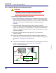
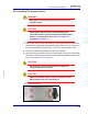
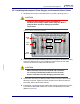
3 Mount the Acoustic Sensor securely to a rigid surface, using the four holes with
M4 thread, to prevent stress at the inlet and outlet tubing welds and seals. See
Figure 2-3 and Figure C-2 on page C-3.
CAUTION
Do not use the inlet and outlet tubing to support the
weight of the Acoustic Sensor.
CAUTION
Maximum allowable depth of screw penetration into the
M4 mounting holes is 6.4 mm (0.25 in.).
Figure 2-3 M4 mounting holes