
User guide

2 - 11
PN 074-566-P1B
Composer Elite Operating Manual
2.2.3 Installing Interconnect, Power Supply, and Communications Cables
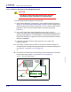
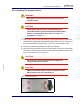
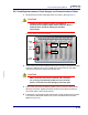
1 Set the Sensor Control Unit power switch to 0 (OFF). (See Figure 2-5.)
CAUTION
Composer Elite contains circuitry susceptible to
transient mains voltages. Make certain Composer Elite is
powered down whenever making any interface
connections.
Figure 2-5 Sensor control unit connections
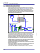
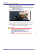
2 Connect the Interconnect Cable(s) male D-sub connector to the Sensor card(s)
connector. (Refer to Figure 2-5.) Tighten the thumb screws on the cable
connector to secure the cable to the Sensor card.
CAUTION
Make certain the Interconnect Cable D-sub connectors
are correctly oriented with the Sensor card / Acoustic
Sensor connectors to avoid damaging connector pins.
3 Connect the Interconnect Cable(s) female D-sub connector to the Acoustic
Sensor(s) connector. Tighten the thumb screws on the cable connector to
secure the cable to the Acoustic Sensor.
4 If applicable, connect the RS-232 cable to the Control card RS-232 connector,
or connect the DeviceNet cable to the Control card DeviceNet connector.
(Refer to Figure 2-5.)
Power
Connector
Power
Switch
Ground
Stud
Sensor Card
Connector
DeviceNet
Connector
RS-232
Connector