
User guide

3 - 14
PN 074-566-P1B
Composer Elite Operating Manual
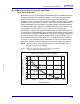
3.3.3 Description of Rear Panel
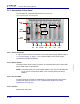
The rear panel of Composer Elite is shown in Figure 3-8.
Figure 3-8 Rear panel of Composer Elite
3.3.3.1 Power Connector
A 4-pin connector used for connection to a 24 V(dc) power supply. Refer to section
1.5.4, Power Supply, on page 1-11 for a full description of the power supply
requirements and pin connections.
3.3.3.2 Power Switch
The power switch is set to ON (I) to power up Composer Elite and it is set to OFF
(O) to power down Composer Elite.
NOTE: The power switch is a circuit breaker rated at 7.5 A. The circuit breaker will
trip on a current overload condition, even if forcibly held in the ON (I)
position.
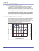
3.3.3.3 Ground Stud
The M4 ground stud is used for establishing an electrical ground to the Sensor
Control Unit. (Refer to section 2.1.2.3, Composer Elite System Grounding
Requirement, on page 2-4.)
3.3.3.4 I/O Slot
Reserved for future use.
Power
Connector
Power
Switch
Ground
I/O
Slot
Control
Slot
Sensor 5
Sensor 1
Slot
Sensor 2
Slot
Sensor 3
Slot
Sensor 4
Slot
Stud
Sensor Card
Connector
DeviceNet
Connector
RS-232
Connector
or I/O Slot