
User Manual

2 - 12
IPN 074-289L
Composer Operating Manual
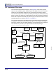
2.5 Instrument Overview
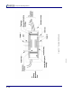
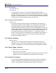
The Instrument System Block Diagram, see Figure 2-5, depicts the general
layout of the complete system. Overall layout first depends on the convenient
location of the Transducer within the flow of the precursor delivery system.
The controller may then be located up to twenty feet away (five feet is preferred)
either in a relay rack, table top, or deployed within the reactor. Power is supplied
either with an optional universal type power supply or from the reactor’s 24 volt
regulated power bus. Refer to section 1.7 on page 1-7.
The controller responds to discrete digital I/O commands and analog set points.
Configuration data is provided at set up through the LCD display or through a
temporary computer link and Setup software. A more expansive and complete
user interface is provided by the optional Monitor software package.
Figure 2-5 Instrument System Block Diagram
Line Voltage
Optional
Power
Supply
LCD Display
IPN 761-600-G2
IPN 761-615-G1 North American
-G2 European
24 V(dc)
Controller
User
Supplied
Computer
Monitor
Software
(Option)
(Option)
IPN 600-1096-G5, G10, or G20
Transducer
Inlet
Gas
Outlet
IPN 761-700-G1
or
Metal O-ringsViton O-rings
Set-up
Software
User
24 V(dc)
Designated for Factory Installation
Rack Mount Kit
Analog I/O
(Option)
LED Display
or
Interconnect Cable
IPN 761-600-G1
IPN 757-212-G1 or G2
IPN 761-601-G1 IPN 761-601-G3