
User Manual

3 - 12
IPN 074-289L
Composer Operating Manual
3.1.13.3 Controller Installation (Bulk Flow)
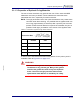
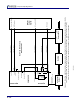
SW#8 of CFGR2 must be activated to use Bulk flow Control. See Figure 3-7 on
page 3-14 for detailed information on proper wiring of the interface. Note the
presence of the 4.99 megohm resistor to ground from the common connection
of relays K4 and K5 on the System I/O Connector. This resistor is necessary to
avoid the Bubbler’s MFC from self-generating a voltage that will drive the
control to the full “on” condition if the Composer is powered off. Other useful
information will be found in the Composer’s Manual sections; section 1.10.1.2
on page 1-11, section 1.10.2 on page 1-11 (all sections) and section 1.10.3 on
page 1-14 (all sections). The ground wires are not shown in Figure 3-7 for
clarity, they must be connected to provide proper references. Be sure the
grounds from the MFC’s power supplies are maintained.
The balance of the interface is provided by the firmware coordinating the action
of two SPST relays. Relay K4 is configured as a Normally Open relay and relay
K5 is configured as Normally Closed. There is a “make before break” sequence
so that the Bubbler’s MFC is never allowed to drop to zero during the toggle
action. The reactor’s connection to Input #4 is now used to initiate a toggle
between the Composer internally or the reactor externally maintaining Bulk
Flow.
During periods of externally (reactor) controlled Bulk Flow the STOP
message is illuminated on the controller’s LCD display and the reactor
generated “CF Setpoint” is passed through relay K5 to the Control Input of
the Bubbler’s MFC. This voltage is also applied to the Composer’s
CONTROL IN connector to allow the Composer to keep track of the
Bubbler’s flow; which aids in quickly acquiring control when transitioning
between reactor and Composer control modes.
When the Composer is actively in control (internal control), the Composer’s
CONTROL OUT signal is routed through relay K4 to the Control Input of the
Bubbler’s MFC, and the CONTROL message is illuminated on the
controller’s LCD display. The Bulk Flow target is determined by the product
of the Concentration Target and the flow setpoint applied to the CONTROL
IN connector by the reactor.
A schematic of the pertinent aspects of a Composer configured for bulk Flow
Control is shown in Figure 3-7 on page 3-14.