Communication Protocol RS232C Serial Interface Cube CDGsci RS232C tira90e1 (2014-01) 1
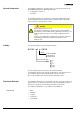
General Information The RS232C Serial Interface for Cube permits the communication between this digital INFICON Capacitance Diaphragm Gauge and • an appropriate controller or • a computer. The RS232C Serial Interface integrated in the Capacitance Diaphragm Gauge allows to digitally transmit measurement values and information on the gauge status as well as to make parameter settings.
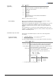
Transmission rate • 9600 Baud DIAG connector assignment • TxD inner pin • RxD middle ring • GND outer ring Response time tira90e1 (2014-01) RS232C.
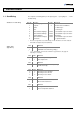
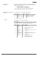
1 Interface Protocol 1.1 Send String Structure of send string The complete send string (frame) is nine bytes (byte 0 … 8) long. Bytes 1 … 7 form the data string. Byte No. 1) Status byte (byte No. 2) Function 0 1 2 Data string length Page No.
Error byte (byte No. 3) Bit No. 0 1 2 3 4 5 6 7 Definition RS232 synchronization error Incorrect command, e.g. inadmissible address (syntax error) Inadmissible read command SP1 status SP2 status Not used Not used Extended error set (→ Read command "Extended Error L-Byte and H-Byte") No bit set → value = 0x00 = no error set Error handling Calculation of pressure value Conversion formula (byte No.
Read command (byte No. 6) All variables in a receipt string that are addressed for reading are output on this byte. For variable types >1 byte, each byte (e.g. low, high, or further bytes) has to be addressed and read individually. Read Command L-Byte → Read Data L-Byte Read Command H-Byte → Read Data H-Byte Checksum and synchronization (byte No. 8) • After a write operation, the value of the addressed variable is output. • After a reset (Power on) the software version is output on byte 6.
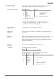
1.2 Receipt String Structure of receipt string Commands to the gauge are transmitted in receipt strings (frames) consisting of five bytes (without ). The data string is formed by bytes 1 … 3. Byte No. Designation 0 1 2 3 4 Value Data string length Data Data Data Checksum of bytes No. 1 … 3 3 (constant value) → "Service command" → "Address byte" → "Data byte" Low byte of checksum 1) 1) Possible high bytes are ignored. • The operation selected in byte No. 1 is addressed in byte No. 2.
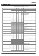
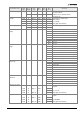
2 Parameter Table All values in this table are quoted in HEX, thus the prefix '0x'. Parameter name Data type DataTxMode uint8 CPU2Unit Filter SP1 Level Low uint8 uint8 sint16 Access Right Byte Type Byte No. 1 Byte No. 2 Byte No.
Parameter name SWDateMonthDay Data type Access Right Byte Type Byte No. 1 Byte No. 2 uint16 R H-Byte 0x00 0xD6 Software version date Month in Hex e.g. 0x03 = March 0xD7 Software version date Day in Hex e.g. 0x19 = 19 L-Byte Part No.
Parameter name SystemDateTime Data type uint8 Access Right Byte Type Byte No. 1 Byte No. 2 R Byte 0 0xE2 0x00 W uint8 R R Byte 1 EthernetLAN uint8 R Set Date and Time. 0xE2 Format: dd.mm.yyyy hh:mm:ss 0xF2 … W uint8 Comment 0xF2 W uint8 Byte No. 3 e.g.
(concluded) Parameter name CPU2Unit Data type uint8 Access Right Byte Type Byte No. 1 R Byte No.
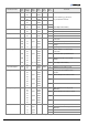
Variables for bytes No. 2 and 3 (special services) Parameter name Data type Byte No. 1 Byte No. 2 Reset uint8 / W 0x40 0x00 Byte No. 3 Comment 0x00 Power reset: Starts continuous pressure output ResetFactory uint8 / W 0x40 0x01 0x00 Factory reset: Sets factory configuration ZeroAdjust uint8 / W 0x40 0x02 – Starts zero offset adjustment W = Write Description of variables Setpoint_level xy Setpoint_level xy = Parameter 1) Setpoint_level xy Zero_Adjust_Value ×a b × F.
DC Output Level The "DC Output Level" variable is used for assigning a defined offset level to the analog output signal, e.g. for setting a certain zero offset signal level. A "DC Output Level" >0 reduces the output range of the measurement range 0 … 10 V by the selected offset value (F.S.R. - DC output level). The "DC Output Level" parameter (16-Bit) consists of the high and low byte.
Original: English tira90e1 (2014-01) t i r a90e1 LI–9496 Balzers Liechtenstein Tel +423 / 388 3111 Fax +423 / 388 3700 reachus@inficon.com www.inficon.