Capacitance Diaphragm Gauge Cube CDGsci Operating Manual Incl.
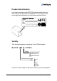
Product Identification In all communications with INFICON, please specify the information given on the product nameplate. For convenient reference copy that information into the space provided below. Model: PN: SN: MAC: V W Validity This document applies to products of the CDGsci series. 3CS1-311-2300 Flange 1 DN 16 ISO-KF 3 DN 16 CF-R E 8VCR female Measurement range (F.S.) 3 6 9 C F 0.1 1 10 100 1000 The part number (PN) can be taken from the product nameplate.
If not indicated otherwise in the legends, the illustrations in this document correspond to gauges with DN 16 ISO-KF vacuum connection. They apply to the other gauges by analogy. We reserve the right to make technical changes without prior notice. Intended Use The temperature compensated Capacitance Diaphragm Gauges of the CDGsci series are intended for absolute pressure measurement of gases in their respective pressure ranges. Functional Principle A ceramic diaphragm is deflected by pressure.
Scope of Delivery 1× gauge CDGsci 1× pin for adjusting settings via buttons 1× Calibration Test Report 1× Operating Manual English 1× Damping unit 2× LEMO connector 1× WLAN USB adapter IEEE822.
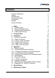
Contents Product Identification Validity Intended Use Functional Principle Trademarks Patents Scope of Delivery 2 2 3 3 3 3 4 1 Safety 1.1 Symbols Used 1.2 Personnel Qualifications 1.3 General Safety Instructions 1.4 Liability and Warranty 7 7 7 8 8 2 Technical Data 9 3 Installation 3.1 Vacuum Connection 3.2 Power Connection 3.2.1 D-Sub, 15-pin Connector 3.2.2 RJ45, 8-pin Connector 3.2.3 LEMO, 2-pin Connector 3.2.4 USB, Typ A Connector 17 17 24 25 26 26 26 4 Operation 4.1 Status Indication 4.
7 Returning the Product 43 8 Disposal 44 9 Accessories 45 Further Information 45 ETL Certification 46 EC Declaration of Conformity 47 For cross-references within this document, the symbol (→ XY) is used, for cross-references to further documents, listed under "Further Information", the symbol (→ [Z]).
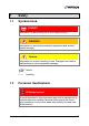
1 Safety 1.1 Symbols Used DANGER Information on preventing any kind of physical injury. WARNING Information on preventing extensive equipment and environmental damage. Caution Information on correct handling or use. Disregard can lead to malfunctions or minor equipment damage. Notice <…> 1.
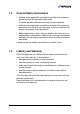
1.3 General Safety Instructions • Adhere to the applicable regulations and take the necessary precautions for the process media used. Consider possible reactions with the product materials. • Adhere to the applicable regulations and take the necessary precautions for all work you are going to do and consider the safety instructions in this document. • Before beginning to work, find out whether any vacuum components are contaminated.
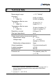
2 Technical Data Measurement range Accuracy 1) 0.1 F.S. 1 … 1000 F.S. Temperature effect on zero 0.1 F.S. 1 … 1000 F.S. Temperature effect on span 0.1 F.S. 1 … 1000 F.S. Resolution, nominal Gas type dependence → 2, "Validity" 0.05% of reading 0.025% of reading 10 ppm F.S./ °C 5 ppm F.S./ °C 10 ppm of reading / °C 5 ppm of reading / °C 0.95 ppm F.S. none Output signal analog (measurement signal) Measurement range 0 … +10 V Voltage range –2 … +10.24 V (limited to +10.
Output signal analog (temperature / atmosphere) Scaling sensor temperature 10 °C – 0.00 V 60 °C – 10.00 V Temp[°C] = 10+5×Aout[V] Scaling atmosphere 1 mbar – 0.005 V 1000 mbar – 5.00 V ATM[Torr] = Aout[V]/5×1000/1.33322 Switchable between temperature and atmosphere via RS232 ASCII, REST services and web interface (→ [1], [2], [4]).
RS232 ASCII interface Transmission rate Data format 9600 baud binary 8 data bits one stop bit no parity bit no handshake → 25 For further information on the RS232 ASCII interface → [2]. RS232C interface Transmission rate Data format 9600 baud binary 8 data bits one stop bit no parity bit no handshake → 25 For further information on the RS232C interface → [3]. Ethernet interface IP address Architecture 192.168.0.
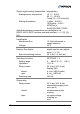
Supply DANGER The gauge may only be connected to power supplies, instruments or control devices that conform to the requirements of a protective extra-low voltage (PELV). The connection to the gauge has to be fused. Grounding concept → 25. Supply voltage at the gauge +14 … +30 V (dc) or ±15 V (±5%) ≤1 Vpp Ripple Power consumption while being heated ≤20 W at operating temperature ≤17 W The gauge is protected against reverse polarity of the supply voltage and overload.
Analog output connection Cable Cable length LEMO plug, 2-pin, with shielding coaxial 2-pin plus shielding ≤1 m (0.05 mm²/conductor) Grounding concept → 25 Materials exposed to vacuum ceramics (Al2O3 ≥99.5%), stainless steel AISI 316L Internal volume DN 16 ISO-KF DN 16 CF-R 8VCR Admissible pressure (absolute) 100 / 1000 F.S. 1 / 10 F.S. 0.1 F.S. Bursting pressure (absolute) Admissible temperatures Storage Operation Relative humidity Use Degree of protection tina88e1-b (2014-09) 5.9 cm3 5.4 cm3 7.
110 (40.1) 190.1 194.5 150 4.
Damping unit [mm] 36 Magnet 90 110 4 × ø5.5 188 200 Weight (without damping unit) tina88e1-b (2014-09) <1.
Analog Measurement Signal vs. Pressure Pressure p 1.1×F.S. 1.0×F.S. 0.9×F.S. 0.8×F.S. 0.7×F.S. 0.6×F.S. 0.5×F.S. 0.4×F.S. 0.3×F.S. 0.2×F.S. 0.1×F.S. 0.0×F.S. 0 1 2 3 4 5 6 7 8 9 10 Measuring signal Uout [V] p = (Uout / 10 V) × p (F.S.) Conversion Torr ↔ Pascal 3) Torr c 1.00 mbar 4) 1013.25 / 760 = 1.3332… Pa 4) 101325 / 760 = 133.3224… Example: Gauge with 10 Torr F.S. Measurement signal Uout = 6 V p = (6 V / 10 V) × 10 Torr = 0.
3 Installation WARNING WARNING: fragile components The ceramic sensor may be damaged by impacts. Do not drop the product and prevent shocks and impacts. 3.1 Vacuum Connection DANGER DANGER: overpressure in the vacuum system >1 bar Injury caused by released parts and harm caused by escaping process gases can result if clamps are opened while the vacuum system is pressurized. Do not open any clamps while the vacuum system is pressurized. Use the type clamps which are suited to overpressure.
DANGER DANGER: protective ground Products that are not correctly connected to ground can be extremely hazardous in the event of a fault. Electrically connect the gauge to the grounded vacuum chamber. This connection must conform to the requirements of a protective connection according to EN 61010: • CF and VCR flanges fulfill this requirement. • For gauges with a KF flange, use a conductive metallic clamping ring.
Mount the gauge so that no vibrations occur. To keep condensates and particles from getting into the measuring chamber preferably choose a upright position. Install the gauge with the damping unit in case of a horizontal mounting orientation (→ 19). The gauge may not be installed in a suspended mounting orientation. In case of severe vibrations at the vacuum system the gauge should be installed with the damping unit.
Carefully remove two covers with e.g. a small screwdriver. Cover Keep the covers.
Carefully slide the gauge with both openings onto the retaining hooks until the mechanical stop is reached … Hook Hook tina88e1-b (2014-09) 21
… and place it on the magnet.
Vacuum connection Remove the protective lid and connect the product to the vacuum system. Seal with centering ring Protective lid Clamp Keep the protective lid.
3.2 Power Connection Make sure the vacuum connection is properly made (→ 17). DANGER The gauge may only be connected to power supplies, instruments or control devices that conform to the requirements of a protective extra-low voltage (PELV). The connection to the gauge has to be fused. Grounding concept → 25. Ground loops, differences of potential, or EMC problems may affect the measurement signal.
3.2.1 D-Sub, 15-pin Connector If no sensor cable is available, make one according to the following diagram (cable length and conductor cross-sections → 12).
3.2.2 RJ45, 8-pin Connector If no Ethernet cable is available, make one according to the following diagram (cable length and conductor cross-sections → 12). Pin 1 Pin 2 Pin 3 Pin 4 Pin 5 Pin 6 Pin 7 Pin 8 3.2.
4 Operation Put the gauge into operation. A warm-up time of at least 90 minutes should be allowed; for precise pressure measurements a warm-up time of at least 4 hours is required. 4.
4.2 Configuring the network interface The network interface can be configured via the wired or the wireless network. 4.2.1 Changing IP Address of the Wired Network The standard IP address of the wired network (default 192.169.0.248 5)) can be changed via • Web interface "Configuration" (→ [4]) • RS232 ASCII interface with command IPL [IP address]|[Subnet mask] (→ [2]): e.g. IPL 10.0.0.200|255.255.255.
Precondition WLAN USB adapter is plugged in (the adapter is enclosed in the scope of delivery). The initialization of the USB adapter takes appr. 30 s. Thereafter the blue LED on the adapter lit solid or is blinking. The wireless network can be activated via • RS232 ASCII interface with command WLA on: SL> WLA on W wla 1 SL> • Ethernet interface with REST services − connect Cube with a computer via Ethernet cable − set the Ethernet interface of the computer to any IP address in the subnet 192.168.0.248|255.
The standard IP address of the wireless network (default 192.168.0.240) can be changed via • web interface "Configuration" (→ [4]) • RS232 ASCII interface with the commands FAP and CAP (→ [2]): SL> FAP e.g. Inficon − Inficon Mobile2 SL>CAP [SSID][|password] e.g. CAP Inficon|mypassword FAP command: Cube will scan available wireless networks. The output is a list of SSIDs (network names). CAP command: Cube will be connected to the wireless network (state SSID and the network password).
An existing wireless network can be displayed by using • the RS232 ASCII command IPW, or • the REST services command http://192.168.0.248:8087/1/cmd/IPW The output is the current IP address and the current network mask (e.g. 10.0.1.6|255.255.255.0). 4.3 Web Interface The gauge is equipped with a web server. Via its web interface user can • poll the status of the gauge, • query gauge errors, • set setpoints, or • change communication parameters (e.g.
4.4 Zeroing the Gauge The gauge is factory calibrated while "standing upright" (→ "Calibration Test Report"). We recommend performing a zero adjustment, when the gauge is operated for the first time. Due to long time operation or contamination, a zero drift could occur and zero adjustment may become necessary. For adjusting the zero, operate the gauge under the same constant ambient conditions and in the same mounting orientation as normally. 4.4.
Evacuate the gauge to a pressure according to the table below: F.S. 1000 100 10 1 0.1 Torr/mbar Torr/mbar Torr/mbar Torr/mbar Torr/mbar Recommended final pressure for zero adjustment <5×10⁻² Torr <5×10⁻³ Torr <5×10⁻⁴ Torr <5×10⁻⁵ Torr <5×10⁻⁶ Torr <6.65×100 Pa <6.65×10⁻¹ Pa <6.65×10⁻² Pa <6.65×10⁻³ Pa <6.65×10⁻⁴ Pa <6.65×10⁻² mbar <6.65×10⁻³ mbar <6.65×10⁻⁴ mbar <6.65×10⁻⁵ mbar <6.65×10⁻⁶ mbar If the final pressure is too high for zero adjustment (>25% of the F.S.
The LED will continue blinking red after 8 s if • the signal output is negative (< -20 mV) when the final pressure has been attained • the zero adjustment has failed. 4.4.2 Adjustment with Ramp Function The ramp function allows to adjust the zero at a known reference pressure within the measurement range of the gauge.
Keep the button depressed max. ø1.1 mm Push the button again: Fine adjustment within 0...3 s: the zero adjustment value changes by one unit (push button in intervals of 1 s) Change of direction within 3...5 s: the zero adjustment changes its direction (the blinking frequency of the LED changes briefly) If the button is released for more than 5 s, the gauge returns to the measurement mode.
4.5 Switching Functions The two switching functions can be set to any pressure within the measurement range of the gauge (→ 16). The current setpoint setting • is output at the analog port instead of the measurement signal (→ 25) and can be measured with a voltmeter after the button is pressed, or • can be read/written via the RS232, Ethernet or wireless interface.
4.5.1 Adjusting the Setpoints The setpoints can be adjusted via • the buttons on the gauge, • the diagnostic port (→ [3]), • the RS232 interface (→ [2], [3]), • the Ethernet interface (→ [1], [4]), • the wireless network (→ [1], [4]). DANGER DANGER: malfunction If processes are controlled via the signal output, keep in mind that by pushing the button the measurement signal is suppressed and the corresponding threshold value is output instead. This can cause malfunctions.
For changing the threshold value, push the button and keep it depressed. The threshold keeps changing from the current value (ramp) until the button is released or until the limit of the setting range is reached. Keep the button depressed max. ø1.1 mm Push the button again: Fine adjustment within 0...3 s: Change of direction within 3...
4.6 Activating the Factory Setting (Factory Reset) All user defined parameters (e.g. zero, filter) are restored to their default values. Loading of the default parameters is irreversible. Loading the default parameters: 4.7 Put the gauge out of operation. Keep the button depressed for at least 5 s while the gauge is being put into operation (Power ON).
5 Deinstallation WARNING WARNING: fragile components The ceramic sensor may be damaged by impacts. Do not drop the product and prevent shocks and impacts. DANGER DANGER: contaminated parts Contaminated parts can be detrimental to health and environment. Before beginning to work, find out whether any parts are contaminated. Adhere to the relevant regulations and take the necessary precautions when handling contaminated parts.
Caution Caution: dirt sensitive area Touching the product or parts thereof with bare hands increases the desorption rate. Always wear clean, lint-free gloves and use clean tools when working in this area. tina88e1-b Vent the vacuum system. Put the gauge out of operation. Unfasten the lock screws and disconnect the sensor cable. Remove the gauge from the vacuum system and install the protective lid.
6 Maintenance, Repair Under clean operating conditions, the product requires no maintenance. Gauge failures due to contamination or wear and tear are not covered by the warranty. We recommend checking the zero at regular intervals (→ 32). The product is equipped with a battery to maintain data integrity of the real-time clock (battery lifetime appr. 10 years). A battery change is necessary, when the real-time clock shows a wrong date.
7 Returning the Product WARNING WARNING: forwarding contaminated products Contaminated products (e.g. radioactive, toxic, caustic or microbiological hazard) can be detrimental to health and environment. Products returned to INFICON should preferably be free of harmful substances. Adhere to the forwarding regulations of all involved countries and forwarding companies and enclose a duly completed declaration of contamination *). *) Form under www.inficon.
8 Disposal DANGER DANGER: contaminated parts Contaminated parts can be detrimental to health and environment. Before beginning to work, find out whether any parts are contaminated. Adhere to the relevant regulations and take the necessary precautions when handling contaminated parts. WARNING WARNING: substances detrimental to the environment Products or parts thereof (mechanical and electric components, operating fluids etc.) can be detrimental to the environment.
9 Accessories Ordering number Communication adapter (2 m) 6) 303-333 Calibration against Level A Standard (PTB Germany) on request Further Information [1] www.inficon.com Communication Protocol REST Services tira88e1 (English only) INFICON AG, LI–9496 Balzers, Liechtenstein [2] www.inficon.com Communication Protocol RS232 ASCII Interface tira89e1 (English only) INFICON AG, LI–9496 Balzers, Liechtenstein [3] www.inficon.
ETL Certification ETL LISTED The product Cube CDGsci 3103457 46 • conforms to the UL Standard UL 61010-1 • is certified to the CSA Standard C22.
EC Declaration of Conformity We, INFICON, hereby declare that the equipment mentioned below complies with the provisions of the Directive relating to electromagnetic compatibility 2004/108/EC and the Directive on the restriction of the use of certain hazardous substances in electrical and electronic equipment 2011/65/EU.
Original: German tina88d1-b (2014-09) t i na88e1- b LI–9496 Balzers Liechtenstein Tel +423 / 388 3111 Fax +423 / 388 3700 reachus@inficon.com www.inficon.