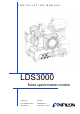
I N S T A L L A T I O N M A N U A L Type designation LDS3000 Product description module Mass spectrometer Catalog no. 560-300 from software version MS Module 1.0 Document no.
This document applies to the software version stated on the cover page. If you need a different version, please contact our sales staff. Reprint, translation and duplication need to be approved in writing by INFICON GmbH.
Content 1 About this manual . . . . . . . . . . . . . . . . . . . . . . . . . . . . . . 5 1.1 1.2 1.3 2 Safety . . . . . . . . . . . . . . . . . . . . . . . . . . . . . . . . . . . . . . . . . 7 2.1 2.2 2.3 2.4 3 4.2 4.3 Construction of the unit . . . . . . . . . . . . . . . . . . . . . . . . . . . . . . . . . . . . 10 4.1.1 MSB box . . . . . . . . . . . . . . . . . . . . . . . . . . . . . . . . . . . . . . . . 11 Function . . . . . . . . . . . . . . . . . . . . . . . . . . . . . . . . . . . . . . . .
6.3 6.4 6.5 6.6 6.7 6.8 6.9 6.10 6.11 6.12 6.13 6.14 6.15 6.16 6.17 6.18 6.19 6.20 7 Maintenance . . . . . . . . . . . . . . . . . . . . . . . . . . . . . . . . . . 43 7.1 7.2 7.3 7.4 8 Content Shutting down the leak detector . . . . . . . . . . . . . . . . . . . . . . . . . . . . . 49 Disposing of the mass spectrometer module . . . . . . . . . . . . . . . . . . . 49 Returning the mass spectrometer module . . . . . . . . . . . . . . . . . . . . . 49 Appendix . . . . . . . . . . . . . . . . . . . . .
1 About this manual 1.1 Target groups This installation manual is intended for the operator and for technically qualified personnel with experience in leak detection technology and integration of leak detection devices in leak detection systems. In addition, the installation and use of the unit require knowledge of electronic interfaces. 1.2 Other applicable documents Control unit operating manual Bus module installation manual I/O module installation manual Interface protocols 1.
1.3.2 6 Text markings Marking Meaning Requirement for execution of an action Tool or aid for an action ► Instruction 1, 2, 3, ...
2 Safety 2.1 Intended use The unit is a modular leak detector for installation in industrial leak detection systems. The test gases that can be measured with the unit are helium and hydrogen (forming gas). The unit is suitable for pressure and vacuum testing. The unit is used for integral testing in a vacuum and for local testing with a sniffer line. ► Install, operate and service the unit only in compliance with this manual. ► Comply with the limits of application (see Chapter 4.3, page 13). 2.
2.4 General safety information The unit was built according to the state of the art and the recognized safety regulations. Nevertheless, improper use can result in danger to life and limb of the user or other persons and damage to the unit and other property. Electric power The unit is operated with electric voltages up to 24 V. Inside the unit there are voltages that are considerably higher. Touching parts where electric voltage is present can result in death.
3 Shipment check, transport, storage Interference with pacemakers The magnets in the mass spectrometer module can affect the proper functioning of pacemakers. ► Always comply with the distances recommended by the pacemaker manufacturer. 3.1 Checking shipment Scope of delivery Article Mass spectrometer module Plug for 24V connection PIRANI gauge Self-locking nuts Plug for OUTPUT Plug for GAUGES EXIT Installation manual USB stick Quantity 1 1 1 4 1 1 1 1 ► Check shipment to make sure it is complete. 3.
4 Description The mass spectrometer module is part of the leak detection system LDS3000. The mass spectrometer module can be operated as part of a test system without the need for additional equipment from INFICON. 4.1 Construction of the unit Fig: 1 Mass spectrometer module LDS3000 1 - Terminal block Connections for test system, backing pump, PIRANI gauge, internal calibration leak and sniffer line.
2- Turbo molecular pump Turbo molecular pump with cooling unit 3 - Pre-amplifier Pre-amplifier of the mass spectrometer module 4 - MSB box Interfaces of the mass spectrometer module (see Chapter 4.1.
3 - GAUGES, EXT Connection for optional external pressure measurement locations (0 ... 10 V or 0 … 20 mA) for INFICON Service Connection plug arrangement 1 2 3 4 5 +24 V output, max. 200 mA Input for P3 service gauge, 0 ...
12 - STATUS Status LED The Power LED and Status LED indicate the status of the unit.
4.3.2 4.3.3 Electrical data Supply voltage 24 V ± 10% DC Power input max. 10 A Physical data Noise level < 60 dB(A) Detectable gases 4 He, H2, Mass 3 (e. g. H-D, 3He or H3) Max. inlet pressure (varying with the operation mode and 0.2 mbar ...
4.3.5 Factory settings Parameter Factory setting Operation mode Vacuum Bus module address 126 Pressure capillary surveillance (min.) 0.4 mbar Pressure capillary surveillance (max.) 2 mbar Pressure unit mbar Emission On Upper limit exponent 1 x 10⁻⁵ Filter leak rate threshold 1 x 10⁻¹⁰ Filter zero time 5s Filter mode I•CAL Gas ballast Off I/O module protocol ASCII Calibration request Off Calibr. factor xxx Mx 1 Calibration factor VAC/SNIF Mx 1.
Description Parameter Factory setting Fan mode Fan always on Machine factor in standby Off Machine factor / Sniff factor 1.0 (for all masses) Mass 4 Maximum pressure VAC 18 mbar Module at I/O connector IO1000 Nominal state TMP On Test leak external SNIF 9.9 x 10⁻² Test leak external VAC 9.9 x 10⁻² Test leak internal 9.9 x 10⁻² Sniff factor 1.
5 Installation 5.1 Rotating the MSB box If required, you can push the MSB box into the mass spectrometer module LDS3000 on the rear side. ► Remove lock of the MSB box. ► Screw lock into the threads on the rear side of the MSB box. ► Disconnect all cables from the MSB box. ► Disconnect all cable clips from the frame. ► Pull out the MSB box. ► Push MSB box on the rear side and turned (with plug markings upside down) into the mass spectrometer module LDS3000. ► Connect all cables to the MSB box.
Self-locking nuts M8 Open-end wrench, size 13 Allen wrench, size 6 Holes for installation inside the test system The mass spectrometer module is delivered with fastening screws and transport nuts already mounted. 1 Remove transport nuts. 2 Drill through-holes: – X distance: 283 mm – Y distance: 121.5 mm – Through-hole in sheet metal: 9 mm – Mounting screws: M8 x 50 Material damage if washers are missing Failure to install the washers can cause the MO bearings to pull out.
5.3 Connecting the mass spectrometer module to the test system The operation mode of the vacuum connection and the speed of the turbo molecular pump define: • Minimum detectable leak rate (MDLR) • Maximum inlet pressure (Pmax) • Volume flow rate (S) Connection Speed turbo molecular pump 1000 Hz 1500 Hz ULTRA MDLR: < 5 x 10-12 mbar·l/s Pmax: 0.2 mbar S: 5 l/s < 1 x 10-11 mbar·l/s 0.2 mbar * 6 l/s FINE MDLR: < 1 x 10-11 mbar·l/s Pmax: 0.9 mbar S: 1.8 l/s < 5 x 10-11 mbar·l/s 0.4 mbar * 2.
5.4 Connection of the connection block 1 Connect PIRANI gauge and backing pump to GROSS/FOREPUMP. 2 Connect the test leak to the second available flange of the vacuum connection. For the unit to operate correctly upon opening of the sniffer valve, no additional line can be connected between the connection block and the sniffer valve or between the sniffer valve and the sniffer line. 3 Connect the sniffer line to FINE. 5.5 Connecting the MSB box Information The connections are close together.
6 Operation You can use the following accessories in combination with the mass spectrometer module: • CU1000 (control unit) • BM1000 (bus module) • IO1000 (I/O module) The following applies to the functions and settings described in this chapter: Accessories Control unit Bus module I/O module Information on Menu Commands Commands Digital input and outputs, Analog outputs Are described in Operating Manual Control Unit CU1000 Interface Protocols LDS3000 Interface Protocols LDS3000 Installation manual
6.2.1 Factory layout Analog output 1: Leak rate mantissa Analog output 2: Leak rate exponent 6.2.2 Possible layouts Off The analog outputs are disabled (output voltage = 0 V). Pressure p1 / Pressure p2 1 ... 10 V; 0.5 V / decade; 1 V = 1 x 10⁻³ mbar Leak rate mantissa 1 ... 10 V; linear; in used unit Information Useful only if the other analog output is assigned “Leak rate exponent”. Leak rate exponent 1 ... 10 V; 0.
Via interface The output voltage can be specified via the LD protocol command 221. Leakage rate Ma. Hys. 0.7 ... 10 V; linear; in used unit Information Useful only if the other analog output is assigned “Leak rate exponent”. This layout prevents the exponent from constantly jumping between two decades. 0.7 V corresponds to a leakage rate of 0.7 x 10-x. 9.9 V corresponds to a leakage rate of 9.9 x 10-x. Pressure p1 (1 V / dec.) / Pressure p2 (1 V / dec.) 1 ... 10 V; 1 V / decade; 2.5 V = 1 x 10⁻³ mbar; 8.
6.2.4 Configuration (LDS2010-compatible) LDS2010 setting in Analog menu item output 22 LDS2010 function LDS3000 function Decade scale 1 Leak rate mantissa in used unit 1 ... 10 V Leak rate mantissa irrelevant irrelevant 1 1 2 2 1 2 2 3 1 3 2 4 1 4 2 5 1 5 2 6 1 6 2 8 1 8 2 24 Operation Leak rate exponent (step function) in used unit Leak rate exponent 1 ... 10 V, 0.5 V/decade, 1 V = 1E-12 Leak rate log. in used unit 1 ... 10 V, 0.5 V/decade, Leak rate log.
LDS2010 setting in Analog menu item output 22 9 1 9 2 10 1 10 2 11 1 11 2 12 1 12 2 13 1 13 2 14 1 14 2 15 1 15 2 16 1 16 2 LDS2010 function Pressure p1 log. in Pa 1 V/decade, 2.5 ... 8.5 V, 2.5 V = 1E-3 mbar Pressure p2 log. in Pa 1 V/decade, 2.5 ... 8.5 V, 2.5 V = 1E-3 mbar Leak rate log. in mbar·l/s 0 ... 8 V, 2 V/decade, 0 V = 1E-3 mbar·l/s Leak rate log. in mbar·l/s 0 ... 10 V, 3 V/decade, 0 V = 1E-3 mbar·l/s Leak rate log. in mbar·l/s 0 ...
LDS2010 setting in Analog menu item output 22 LDS2010 function Leak rate log. in mbar·l/s 0 ... 8 V, 2 V/decade, 0 V = 1E-10 mbar·l/s Leak rate log. in mbar·l/s 0 ... 10 V, 3 V/decade, 0 V = 1E-10 mbar·l/s Leak rate log. in mbar·l/s 0 ... 8 V, 2 V/decade, 0 V = 1E-11 mbar·l/s Leak rate log. in mbar·l/s 0 ... 10 V, 3 V/decade, 0 V = 1E-11 mbar·l/s LDS3000 function Decade scale Upper limit value (10 V = ...) Leak rate log. 2 V/dec. 1E-5 mbar·l/s Leak rate log. Special_1 1E-6 mbar·l/s Leak rate log.
LDS2010 setting in Analog menu item output 22 LDS2010 function LDS3000 function Decade scale Upper limit value (10 V = ...) 26 2 Leak rate log. in mbar·l/s 0 ... 4 V, 1 V/decade, 0 V = 1E-9 mbar·l/s Leak rate log. 1 V/dec. 1E1 mbar·l/s 27 1 Leak rate lin. in mbar·l/s 0 ... 10 V, 1 V = 1E-7 mbar·l/s Leak rate linear irrelevant 1E-6 mbar·l/s 27 2 Leak rate log. in mbar·l/s 0 ... 4 V, 1 V/decade, 0 V = 1E-10 mbar·l/s Leak rate log. 1 V/dec. 28 1 Leak rate lin. in mbar·l/s 0 ...
Function Flank/state: Description inactive→ active: Switch to Standby. (ZERO is not possible, all trigger outputs will return "Fail".) STOP ZERO ZERO_PULS CLEAR GASBALLAST SELECT_DYN_NORMAL START_STOP KEY_1 KEY_2 KEY_3 inactive→ active: Switch ZERO on. active→ inactive: Switch ZERO off. inactive→ active. Switch ZERO on or off. inactive→ active: Erase warning or error message / cancel calibration. inactive→ active: Open gas ballast valve. active→ inactive: Close gas ballast valve unless always open.
Function WARNING ERROR CAL_ACTIVE CAL_REQUEST RUN_UP ZERO_ACTIVE EMISSION_ON MEASURE State: closed: open: closed: open: closed: open: closed: closed: open: closed: open: closed: open: closed: open: closed: open: closed: STANDBY SNIFF open: closed: open: Description Warning no warning Error no error Unit is calibrated. Unit is not calibrated. and no external calibration: Calibration request (e. g.
6.5 Starting/stopping the measurement During the measurement ZERO is possible. During standby ZERO is not possible. The output at the trigger outputs is: The trigger outputs switch depending on Leakage rate value exceeded the leakage rate and the trigger threshold. threshold. Sniff is possible. Sniff is not possible. Calibration using PLC input or output will Calibration using PLC input and output start an external calibration. will start an internal calibration.
6.8 Activate/deactivate ZERO ZERO can be used to suppress undesired helium backgrounds. If ZERO is enabled, the currently measured leakage rate value will be interpreted as a helium background and subtracted from all subsequently measured values. The background value suppressed by ZERO is adjusted automatically if the background changes inside the unit. Information If the signal filter Fixed or 2-Zone is selected, then the background value is automatically adjusted based on the configured zero time.
6.10 Calibrating the unit ► To ensure measuring accuracy, the unit must be calibrated regularly. Information Recalibration at the start of every shift is recommended. Incorrect measurement results due to premature calibration If calibrated prematurely, the unit will produce incorrect measurement results. ► Allow the unit to run for at least 20 minutes before performing the calibration.
6.10.1 Internal calibration Internal test leak connected. 1 Enter leakage rate of the test leak via digital interface (control unit CU1000, I/O module IO1000 or bus module BM1000). 2 Start calibration. Calibration is performed automatically. 6.10.2 External calibration Vacuum mode: External test leak installed and open in or on the test system. Sniffer mode: Sniffer line measures sniffer leak.
6.10.3 Enable/disable Calibration request If Calibration request is enabled, the unit will prompt the user to perform a calibration 30 minutes after it has been switched on and in case of temperature changes greater than 5 °C. ► Enable or disable Calibration request as needed: FUNCTIONS > CAL > SETTINGS > CAL REQUEST > CALIBRATION REQUEST 6.10.
6.11 Select sample gas The mass spectrometer module is capable of measuring the following gases: • Hydrogen (H2) • Mass 3 (H-D, 3He oder H3) • Helium (4He) ► Select desired mass: SETTINGS > MASS > MASS The machine, calibration and sniff factor are dependent on the configured mass and are saved in the mass spectrometer module. 6.12 Decontaminating backing pump from test gas The mass spectrometer module can control an electric 24V gas ballast valve of the backing pump via the OUTPUT connection.
6.15 Enable/disable correction of the leakage rate in Standby Enabled = machine/sniff factor is considered in Standby. Disable = machine/sniff factor is not considered in Standby. ► Enable or disable correction of the leakage rate in Standby as needed: SETTINGS > SET UP > OPERATION MODES > LR CORRECTION > MACHINE FACTOR IN STANDBY 6.16 Setting the leakage rate threshold value The mass spectrometer module has four independent leakage rate threshold values.
Error number Error number Limit Cause ASCII values protocol* Jumper for clock not set, Clock is not set 16 16 battery drained, clock defective No answer from bus Connection to BUS module 99 99 module interrupted I/O module Connection to I/O module 99 99 interrupted disconnected Wrong bootloader Boot loader not compatible 99 99 version with application Sniffer not connected 99 99 2xx operating voltage error U24VHz too low 24 120 21.6V 24V power supply pack (voltage [V]) U24VHz too high, 24 120 26.
Error number Limit Cause ASCII values protocol* +15V or REV5V too low, Voltage REF5V short circuit at preE shortened, 24 120 amplifier, IF board or MSB (voltage [V]) defective 3xx detection system (offset pre-amplifier, pre-amplifier test, emission, cathode test) Short circuit anode voltage, pressure in mass 7V < Anode voltage too low, W 41 132 Nom. spectrometer too high, IF (anode voltage [V]) Value board, MSB or ion source defective 7V > Anode voltage too high, W 40 131 Nom.
Error number Error number Limit Cause values ASCII protocol* <-70 mV Poor ion source or Preamp output too low at contaminated mass 31 123 (preamp voltage [V]) 500 GΩ spectrometer >+/-50 mV at 500 GΩ, >+/-10 mV at 15 GΩ, Preamp offset too high 31 123 Pre-amplifier defective <+/-10 mV (Offset [V]) at 470 MΩ, <+/-9 mV at 13 MΩ Preamp range error Pre-amplifier or MSB box 31 123 (preamp voltage [V]) defective Pre-amplifier defective, 500 G out of range, 450 GΩ 31 123 error at the suppressor, IF (resistor [Ω]) 5
Error number 40 Error Error number number LDS1000 ASCII protocol protocol* 5xx Pressure and flow errors Pressure sensor not connected, 58 144 (pressure p1 voltage [V]) Pressure too high, 73 148 (pressure p1 [mbar]) Pressure rise, anode break down, 73 148 (anode voltage [V]) Warning/ Error message Error LDS3000 500 W 520 W 521 W 522 W Pressure rise emission break down, (emission current [A]) 73 148 540 W Pressure too low, sniffer blocked, (pressure p1 [mbar]) 63 62 541 E 542 W 600 W
Error number Error number Limit Cause ASCII values protocol* Machine factor adjustment Machine factor too high, 1.00E+ inaccurate, split flow factor 81 153 04 (machine factor) too high Machine factor lower < 50% Split flow factor has than last, 81 153 old changed (machine factor) value Machine factor higher > 200% Split flow factor has than last, 81 153 old changed (machine factor) value Leakage rate of internal Int testleak not set, 0 0 test leak is still set to (int.
6.20.1 Error codes of the status LED Any errors or warnings occurring in the MSB box will be indicated both as an error code by the control unit and as a blink code by the Status LED. The blink code is preceded by a long white signal. This is followed by an error or warning number.
7 Maintenance The mass spectrometer module is a leak detector that is intended for industrial applications. The unit is composed of parts and assemblies that are, for the most part, low maintenance. Servicing the mass spectrometer module merely requires that you change the operating fluid reservoir of the turbo molecular pump and check the fan on the turbo molecular pump. Information We recommend that you sign a service agreement with INFICON or one of INFICON's authorized service partners. 7.
Danger to life due to electric shock Inside the unit there are voltages of considerable magnitude. Touching parts where electric voltage is present can result in death. ► Disconnect the unit from the power supply prior to any maintenance work. Material damage due to unclean working conditions Unclean working conditions can damage the unit. ► Make sure that the working environment is clean and you use clean tools whenever performing any maintenance work. 7.
7.4 Maintenance steps 7.4.1 Change operating fluid reservoir of turbo molecular pump 1 Shut down mass spectrometer module, see Chapter 8, page 49. 2 Remove turbo molecular pump. Fig: 5 1 2 Turbo molecular pump SplitFlow 80 Cover O-ring 3 4 Operating fluid reservoir Ventilation screw Flooding mass spectrometer and turbo molecular pump The cover of the operating fluid reservoir cannot be unscrewed unless the reservoir has been flooded. 1 Disconnect 24 V power supply pack from MSB box.
Removing old operating fluid reservoir Face pin wrench, P/N: 551-200 Two screwdrivers Tweezers O-ring Operating fluid reservoir, P/N: 200 003 801 Mass spectrometer and turbo molecular pump flooded. 1 Pay attention to the expiration date of the new operating fluid reservoir. Danger of poisoning due to harmful substances The operating fluid reservoir and parts of the turbo molecular pump can be contaminated with toxic substances that are contained in the pumped media.
Fig: 6 1 2 Changing the operating fluid reservoir O-ring Operating fluid reservoir 3 4 Porex rods Ventilation screw Replacing Porex rods 1 Pull out the old Porex rods (8 pcs) using a pair of tweezers. Material damage due to cleaning liquids Cleaning liquids can damage the unit. ► Do not use any cleaning liquids. ► Use a clean, lint-free cloth. 2 Remove any contaminants found on the turbo molecular pump and the cover using a clean, lint-free cloth.
Inserting a new operating fluid reservoir The new operating fluid reservoir will be positioned correctly when you screw in the cover: 1 Do not slide in the new operating fluid reservoir into the pump completely, but stop once you reach the o-ring. 2 Use a face pin wrench to screw in the cover. Material damage if o-ring is mounted improperly An improperly mounted o-ring can cause leaks. The unit will experience malfunctions and become damaged. ► Insert the o-ring carefully. 3 Insert a new o-ring.
8 Taking out of service 8.1 Shutting down the leak detector 1 Switch off the leak detector on the power supply pack. 2 Wait until the turbo molecular pump has stopped running. 8.2 Disposing of the mass spectrometer module The unit can be disposed of by the user or sent to INFICON. Information The unit is made of materials that can be reused. By recycling these materials you reduce waste and environmental impact. ► For disposal, always comply with local and regional environmental and safety regulations.
9 Appendix 9.
9.2 Declaration of Contamination Declaration of Contamination The service, repair, and/or disposal of vacuum equipment and components will only be carried out if a correctly completed declaration has been submitted. Non-completion will result in delay. This declaration may only be completed (in block letters) and signed by authorized and qualified staff. Description of product Reason for return Type Article Number Serial Number Operating fluid(s) used (Must be drained before shipping.
INFICON GmbH, Bonner Strasse 498, D-50968 Cologne, Germany UNITED STATES TAIWAN JAPAN KOREA SINGAPORE GERMANY FRANCE UNITED KINGDOM HONG KONG Vi sit o ur we bsi t e fo r con t act i nfo rm ati on an d o t her sal es o ffice s wo rl dw id e. w w w . i n f i c o n .