
Install Instructions
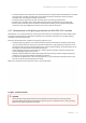


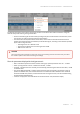
Table Of Contents
- About This Manual
- Important Notice
- Introduction
- Document structure
- Document marks
- Key Features
- Hardware Platform
- Power supply
- Lightning protection unit
- Synchronization unit
- // 0) { /* For each inline-commented element clear data-ref and class */ for (var i=0; i < commentedElements.length; i++) { commentedElements[i].dataset.ref= ""; commentedElements[i].className = ""; } } /* Else do nothing */ } }); //]> AUX-ODU-SYNC Mounting
- AUX-ODU-SYNC Cable gland Assembling
- AUX-ODU-SYNC Connection to ODU
- Packing List
- Planning considerations
- Link Pre-configuration in the lab
- Installation
- Operation & Administration
- Troubleshooting
- Glossary

Infinet Wireless: Technical Documentation – InfiMAN Evolution
Installation – 51
•
•
•
•
•
•
•
•
The end of the FTP service cable that is connected to the power supply should be assembled with a shielded
RJ-45 connector. The other end of the FTP service cable (connected to the wireless device) should be
assembled with unshielded (standard) RJ-45 connector.
The power supply is grounded via a three-conductor power cord and a grounded socket.
AUX-ODU-LPU-L, AUX-ODU-LPU-G and wireless device grounding is performed using grounding bolt.
Antenna pole and wireless device should be connected to the common ground ring. Grounding cables
should be no less than 10AWG thick and must use corrosion-resistant connectors.
6.4.2 Requirements to the lightning protection unitAUX-ODU-LPU-Llocation
AUX-ODU-LPU-Lis an optional accessory which may be used to serve as a line protection unit for theODUand for
the indoor network equipment connected to the Ethernet port of theIDU. AUX-ODU-LPU-Lshould be properly
assembled, mounted and grounded.
General recommendations for installations of lightning protection units:
Install the lightning protection unit on both ends of the cable to protect both the outdoor and the indoor
unit.The purpose of theLPUat the top is to protect theODUfrom a surge of lightning strike which can hit
the long FTP cablerun along the height of the pole or on the roof of the building.The purpose of theLPUat
the bottom is to protect theIDUand customer equipment.
Use the lightning protection unit to protect all circuits for signal transmission and power supply (video,
audio, management signals, Ethernet, etc.)
Regularly (especially before the periods with high thunderstorm activity) check the integrity of lightning
protection units, grounding elements andbonding conductors.
The ports of the AUX-ODU-LPU-L device are symmetrical, i.e. the correspondence of ports position to the
external unit and the power supply does not matter.
Make sure to install the twoLPUdevices as shown in the scheme below.
11 Figure - Connection scheme
CAUTION
Please note grounding cables should not be connected to the mast. All devices must use separate
grounding cable that should be connected to the grounding circuit. The best scenario is when grounding
cables are lined parallel to the Ethernet cable.