
Install Instructions
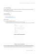
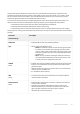
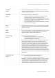
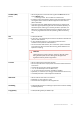
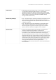
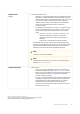
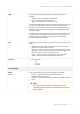
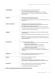
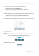
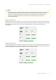
Table Of Contents
- About This Manual
- Important Notice
- Introduction
- Document structure
- Document marks
- Key Features
- Hardware Platform
- Power supply
- Lightning protection unit
- Synchronization unit
- // 0) { /* For each inline-commented element clear data-ref and class */ for (var i=0; i < commentedElements.length; i++) { commentedElements[i].dataset.ref= ""; commentedElements[i].className = ""; } } /* Else do nothing */ } }); //]> AUX-ODU-SYNC Mounting
- AUX-ODU-SYNC Cable gland Assembling
- AUX-ODU-SYNC Connection to ODU
- Packing List
- Planning considerations
- Link Pre-configuration in the lab
- Installation
- Operation & Administration
- Troubleshooting
- Glossary

Infinet Wireless: Technical Documentation – InfiMAN Evolution
Operation & Administration – 99
•
•
•
•
•
•
•
•
On each radio profile, the following options are available (for theSlaveunit only):
"Disable profile" check box disable a radio profile
Add a new radio profile by clicking the «Add Profile» button
Copy the radio profile values to a new radio profile by clicking the «Copy» button
Remove the radio profile by clicking the «Remove» button.
Frequency limitation
The licensed frequencies range per each bandwidth is displayed in the "rf6.0" subsection, in “Default Frequency
Grid” fields. Changes to these default values can be performed in the “Customer Frequency Grid” fields; you can:
Limit the licensed frequencies range per each bandwidth (see the screenshot below)
Change the center frequency step (for example: 5920-6040/20 means that the step between the center
frequencies from 5920 GHz and 6040 GHz is 20 MHz).
The changes performed in “Customer Frequency Grid” will be available in the “Frequency” drop down list from the
radio profiles and inDFS(see page 137)page in “Frequency grid” field.
58 Figure - Customer frequency grid
Setting channel type mode
When Channel Type is set to “Single”, thenTxand/orRx of Chain #1(for horizontal polarization antenna) can be
deactivated:
"Chain #0" is connected to the port of the vertical polarized integrated antenna
"Chain #1" is connected to the port of the horizontal polarized integrated antenna
59 Figure - Configuration options
If the "Single" mode is selected when, then "Chain #1" column (horizontal polarization) can be disabled for
transmission (TX) and / or reception (RX):
60 Figure - Chain #