
Datasheet


Data Sheet 27 Rev. 2.4, 2007-08-08
TLE6288R
Application Information
7 Application Information
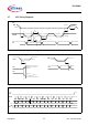
7.1 Z
thjc
Diagram Junction - Case for Single channel operation
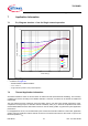
Figure 18 Z
thjc
Diagram
• Conditions for Figure 18
– Results based on FEM Simulations
–
T
case
= 125 °C
–
Single Channel operation, 0.8W power dissipation
7.2 Thermal Application Information
All thermal resistance values in this document are data from FEM (Finite Element Modelling). The boundary
conditions are chosen according to the JESD51 standard. Therefore, all values can be viewed as reliable and
reproducible.
The high effective thermal conductivity test PCB (2s2p) gives a near best case thermal performance value.
compared to the single layer low effective thermal conductivity PCB (1s). It should be emphasized that values
measured/simulated with these test boards cannot be used to directly predict any particular system application
performance.
In real applications, the
R
thjA
can be influenced by the environment and PCB conditions. Thermal vias, application
specific multi layer PCBs and a direct thermal connection to the ECU metal-case are often used to improve the
thermal impedance
R
thjA
.
0,01
0,1
1
10
0,000001 0,00001 0,0001 0,001 0,01 0,1
Pulse width [s]
Zth(D, Pulse width) [K/W
]
0,5
0,2
0,1
0,05
0,02
0,01
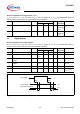
Dutycycle D