
Datasheet


Data Sheet 5 Rev. 2.4, 2007-08-08
TLE6288R
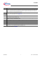
Pin Configuration
2 Pin Configuration
2.1 Pin Assignment
Figure 2 Pin Configuration PG-DSO-36-26
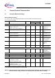
2.2 Pin Definitions and Functions
Pin Symbol Function
1 SOUT4 Source Output CH 4 (high/low side)
2 DOUT4 Drain Output CH 4 (high/low side)
3 DOUT1 Drain Output CH 1 (high side)
4 SOUT1 Source Output CH 1 (high side)
5 IN4 Control Input Channel 4
6 IN1 Control Input Channel 1
7 DIAG1 Diagnostic Output CH 1
8 DIAG2 Diagnostic Output CH 2
9 DIAG3 Diagnostic Output CH 3
10 DIAG4 Diagnostic Output CH 4
11 DIAG5 Diagnostic Output CH 5
12 DIAG6/Overtemp Diagnostic Output CH 6 / Overtemp
13 IN2 Control Input Channel 2
14 IN5 Control Input Channel 5
15 SOUT2 Source Output CH 2 (high side)
16 DOUT2 Drain Output CH 2 (high side)