
Datasheet


TLE6288R
Pin Configuration
Data Sheet 6 Rev. 2.4, 2007-08-08
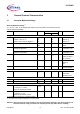
2.3 Pin Description
17 DOUT5 Drain Output CH 5 (high/low side)
18 SOUT5 Source Output CH 5 (high/low side)
19 SOUT3 Source Output CH 3 (high side)
20 DOUT3 Drain Output CH 3 (high side)
21 VCP Charge Pump capacitor pin
22 FSIN All Channels Enable/Disable
23 GND Logic Ground
24 Fault General Fault Flag
25 IN3 Control Input Channel 3
26 IN6 Control Input Channel 6
27 Reset Reset pin (+ Standby Mode)
28
V
CC
Logic Supply Voltage (5 V)
29
V
DO
Supply pin for digital outputs
30 SO SPI Serial Data Output
31 CLKProg Program pin of SPI Clock
32 SCLK SPI Serial Clock
33 CS SPI Chip Select
34 SI SPI Serial Data Input
35 DOUT6 Drain Output CH 6 (high/low side)
36 SOUT6 Source Output CH 6 (high/low side)
Symbol Description
DOUT1-3 Drain of the 3 highside channels. These pins must always be connected to the same power (battery)
supply line (
V
B
).
SOUT1-3 Source of the 3 highside channels. Outputs of the highside channels where the load is connected.
DOUT4-6 Drain pins of the 3 configurable channels. In highside configuration they must be connected to the
same voltage as DOUT1-3. In lowside configuration they are the output pins and connected to the
load.
SOUT4-6 Source of the 3 configurable channels. In highside configuration they are the outputs and connected
to the load. In lowside configuration they must be connected with GND.
IN1-6 Parallel input pins for the 6 power outputs. These pins have an internal pull-down structure.
GND Logic ground pin, the heat slug has to be connected to this potential.
FSIN Disable pin. If the FSIN pin is in a logic low state, it switches all outputs OFF. The pin has an internal
pull-up structure.
Reset Reset pin. When the reset is low all channels are off, the internal biasing is deactivated, all internal
registers are cleared and the supply-current consumption is reduced (standby mode). The pin has an
internal pull-up structure.
Fault General Fault pin. There is a general fault pin (open drain) which shows a high to low transition as
soon as an error is latched into the diagnosis register. When the diagnosis register is cleared this flag
is also reset (high ohmic). This fault indication can be used to generate a µC interrupt.
Pin Symbol Function