
Datasheet


IFX1050G
Pin Configuration
Data Sheet 5 Rev. 1.0, 2009-05-14
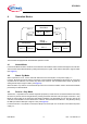
3 Pin Configuration
3.1 Pin Assignment
Figure 2 Pin Configuration
3.2 Pin Definitions and Functions
Pin Symbol Function
1TxD CAN transmit data input;
20 kΩ pull - up, “LOW” in dominant state
2GND Ground
3
V
CC
5 V Supply input
4RxD CAN receive data output;
“LOW” in dominant state,
integrated pull - up
5RM Receive - Only input;
control input, integrated 20 kΩ pull - up,
“LOW” to activate Receive - Only Mode
6CANL Low line I/O;
“LOW” in dominant state
7CANH High line I/O;
“HIGH” in dominant state
8INH Inhibit Input;
control input, 20 kΩ pull - up,
“LOW” to activate Normal Mode
3,1&21),*B,);69*
7['
*1'
9
&&
5['
&$1+
&$1/
,1+
50