
Datasheet

www.irf.com 1
6/29/04
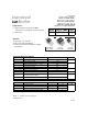
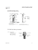
IRF3704ZPbF
IRF3704ZSPbF
IRF3704ZLPbF
HEXFET
®
Power MOSFET
Notes through are on page 12
Applications
Benefits
l Low R
DS(on)
at 4.5V V
GS
l Ultra-Low Gate Impedance
l Fully Characterized Avalanche Voltage
and Current
l High Frequency Synchronous Buck
Converters for Computer Processor Power
l Lead-Free
PD - 95463
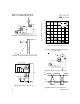
D
2
Pak
IRF3704ZS
TO-220AB
IRF3704Z
TO-262
IRF3704ZL
V
DSS
R
DS(on)
max
Qg
20V
7.9m
:
8.7nC
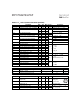
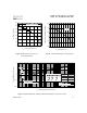
Absolute Maximum Ratings
Parameter Units
V
DS
Drain-to-Source Voltage V
V
GS
Gate-to-Source Voltage
I
D
@ T
C
= 25°C
Continuous Drain Current, V
GS
@ 10V
A
I
D
@ T
C
= 100°C
Continuous Drain Current, V
GS
@ 10V
I
DM
Pulsed Drain
C
urrent
P
D
@T
C
= 25°C
Maximum Power Dissipation W
P
D
@T
C
= 100°C
Maximum Power Dissipation
Linear Derating Factor W/°C
T
J
Operating Junction and °C
T
STG
Storage Temperature Range
Soldering Temperature, for 10 seconds
Mountin
g
Torque, 6-32 or M3 screw
Thermal Resistance
Parameter Typ. Max. Units
R
θ
JC
Junction-to-Case
––– 2.65 °C/W
R
θ
CS
Case-to-Sink, Flat Greased Surface
0.50 –––
R
θ
JA
Junction-to-Ambient
––– 62
R
θ
JA
Junction-to-Ambient (PCB Mount)
––– 40
10 lbf
in (1.1N m)
300 (1.6mm from case)
-55 to + 175
57
0.38
28
Max.
67
47
260
± 20
20