
Datasheet

06/24/11
IRFH5010PbF
HEXFET
®
Power MOSFET
Notes through are on page 8
Features and Benefits
www.irf.com 1
Features
Benefits
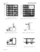
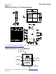
PQFN 5X6 mm
Applications
• Secondary Side Synchronous Rectification
• Inverters for DC Motors
• DC-DC Brick Applications
Note
Form
Quantity
IRFH5010TRPBF
PQFN 5mm x 6mm
Tape and Reel
4000
IRFH5010TR2PBF
PQFN 5mm x 6mm
Tape and Reel
400
Orderable part number Package Type
Standard Pack
Low RDSon (< 9 m
Ω
)
Lower Conduction Losses
Low Thermal Resistance to PCB (<0.5°C/W)
Increased Power Density
100% Rg tested
Increased Reliability
Low Profile (<0.9 mm)
results in
Increased Power Density
Industry-Standard Pinout
⇒
Multi-Vendor Compatibility
Compatible with Existing Surface Mount Techniques
Easier Manufacturing
RoHS Compliant Containing no Lead, no Bromide and no Halogen
Environmentally Friendlier
MSL1, Industrial Qualification
Increased Reliability
Absolute Maximum Ratings
Parameter Units
V
DS
Drain-to-Source Voltage
V
GS
Gate-to-Source Voltage
I
D
@ T
A
= 25°C
Continuous Drain Current, V
GS
@ 10V
I
D
@ T
A
= 70°C
Continuous Drain Current, V
GS
@ 10V
I
D
@ T
C(Bottom)
= 25°C
Continuous Drain Current, V
GS
@ 10V
I
D
@ T
C(Bottom)
= 100°C
Continuous Drain Current, V
GS
@ 10V
I
DM
Pulsed Drain Current
P
D
@T
A
= 25°C
Power Dissipation
P
D
@ T
C(Bottom)
= 25°C
Power Dissipation
Linear Derating Factor
W/°C
T
J
Operating Junction and
T
STG
Storage Temperature Range
-55 to + 150
3.6
0.029
250
Max.
13
70
400
± 20
100
11
100
V
W
A
°C
V
DS
100 V
R
DS(on) max
(@V
GS
= 10V)
9.0
m
Ω
Q
g (typical)
67
nC
R
G (typical)
1.2
Ω
I
D
(@T
c(Bottom)
= 25°C)
100 A
PD-96297A