X MC11 00 CPU Car d For XMC1000 Family CPU- 11A- V1 XMC1100 CPU Card Boar d User ' s Manu a l Revision 2.
Edition 2013-12-18 Published by Infineon Technologies AG 81726 Munich, Germany © 2013 Infineon Technologies AG All Rights Reserved. Legal Disclaimer The information given in this document shall in no event be regarded as a guarantee of conditions or characteristics.
CPU-11A-V1 XMC1100 CPU Card Revision History Page or Item Subjects (major changes since previous revision) Revision 2.0, 2013-12-18 16,18 Change C210 to 4.
CPU-11A-V1 XMC1100 CPU Card Table of Contents 1 1.1 1.2 Overview ........................................................................................................................................ 7 Key Features .................................................................................................................................. 7 Block Diagram................................................................................................................................. 7 2 2.1 2.1.1 2.
CPU-11A-V1 XMC1100 CPU Card List of Figures Figure 1 Figure 2 Figure 3 Figure 4 Figure 5 Figure 6 Figure 7 Figure 8 Figure 9 Figure 10 Figure 11 TM Block Diagram of XMC1100 CPU Card for Arduino ...................................................................... 7 TM XMC1100 CPU Card for Arduino .................................................................................................. 8 Digital IO connectors IOH, IOL ..............................................................................
CPU-11A-V1 XMC1100 CPU Card List of Tables Table 1 Table 2 Table 3 Table 4 Table 5 Table 6 Table 7 Table 8 Table 9 Digital IO of connector IOH.............................................................................................................. 9 Digital IO of connector IOL .............................................................................................................. 9 Pinout of the AD connector........................................................................................
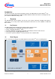
CPU-11A-V1 XMC1100 CPU Card Introduction TM This document describes the features and hardware details of the XMC1100 CPU Card for Arduino . This ® TM board is mounted with ARM Cortex -M0 based XMC1100 Microcontroller from Infineon Technologies AG and part of Infineon’s XMC1000 offering of Kits. 1 Overview TM TM The XMC1100 CPU Card for Arduino has two rows of pin headers which fully compatible with Arduino shield.
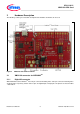
CPU-11A-V1 XMC1100 CPU Card 2 Hardware Description The following sections give a detailed description of the hardware and how it can be used. Figure 2 TM XMC1100 CPU Card for Arduino 2.1 XMC1100 connector for ARDUINO 2.1.1 Digital IO connector TM TM XMC1100 CPU Card for Arduino have 10 pin connector mounting holes and 8 pin connector mounting holes at IOH and IOL respectively. Sixteen of those pins are digital input or output pins. The pinouts are listed in Table 1 and Table 2.
CPU-11A-V1 XMC1100 CPU Card Figure 3 Table 1 Digital IO connectors IOH, IOL Digital IO of connector IOH TM Pin No. Arduino 10 SCL P2.0 I C Clock 9 SDA P2.1 8 AREF P2.3 I C Data / Address Analog reference voltage 7 6 GND 13 - SCK GND P0.7 Ground SPI-SCK / LED output 5 4 3 2 1 12 - MISO ~11 - MOSI ~10 - SS ~9 8 P1.0 P1.1 P0.9 P0.8 P0.12 SPI-MISO SPI-MOSI / PWM output SPI-SS / PWM output PWM output GPIO Table 2 Pin No.
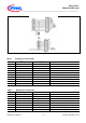
CPU-11A-V1 XMC1100 CPU Card 2.1.2 Analog input TM XMC1100 CPU Card for Arduino Figure 4 Table 3 Pin No. has six analog inputs at connector AD. Analog input AD connector Pinout of the AD connector TM Arduino Signal Name XMC1100 Signal Name Description 1 2 3 4 5 A0 A1 A2 A3 A4 P2.6 P2.8 P2.9 P2.10 P2.11 ADC Input ADC Input ADC Input ADC Input ADC Input 6 A5 P2.2 ADC Input 2.1.
CPU-11A-V1 XMC1100 CPU Card Figure 5 Table 4 POWER connector Pinout of the POWER connector TM Pin No. Arduino 1 2 3 4 IOREF AREF 3.3V VDDP P2.4 +3V3 5 5V +5V 6 7 8 GND GND VIN GND GND VIN 2.1.4 Signal Name XMC1100 Signal Name Description VDDP connect to 5V via R102 ADC input to sense Analog reference voltage 3.3V is generated by a 3.3V regulator IC101 from +5V +5V is generated by the 5V regulator IC102 from VIN input. If VIN is not powered, +5V is supply by micro-USB connector.
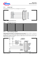
CPU-11A-V1 XMC1100 CPU Card Figure 7 Table 6 LEDs Circuit LEDs Signal Description LED Designation Signal Name Description LED102 LED103 LED104 LED105 LED106 P0.7 P0.5 P0.6 P1.2 P1.3 Output ‘High’ to on LED Output ‘Low’ to on LED Output ‘Low’ to on LED Output ‘Low’ to on LED Output ‘Low’ to on LED LED107 LED108 P1.4 P1.5 Output ‘Low’ to on LED Output ‘Low’ to on LED 2.
CPU-11A-V1 XMC1100 CPU Card Table 7 Signals of connector AD_AUX Pin No. Signal Name Description 1 2 3 P2.7 P2.5 GND ADC input ADC input ADC input Table 8 Signals of connector AUX Pin No. 1 2 3 Signal Name P0.5 P0.6 P0.10 Description GPIO GPIO GPIO 4 5 P0.11 P0.13 GPIO GPIO Board User's Manual 13 Revision 2.
CPU-11A-V1 XMC1100 CPU Card 3 Production Data 3.1 Schematics TM This chapter contains the schematics for the XMC1100 CPU Card for Arduino : Figure 9: CPU, Pin Headers, LED, Power Supply Figure 10: On-board Debugger, Power Board User's Manual 14 Revision 2.
CPU-11A-V1 XMC1100 CPU Card Figure 9 TM Schematic 1 of 2 XMC1100 CPU Card for Arduino Board User's Manual 15 Revision 2.
CPU-11A-V1 XMC1100 CPU Card Figure 10 TM Schematic 2 of 2 XMC1100 CPU Card for Arduino Board User's Manual 16 Revision 2.
CPU-11A-V1 XMC1100 CPU Card 3.2 Layout and Geometry Figure 11 TM XMC1100 CPU Card for Arduino 3.3 layout and geometry Bill of Material TM Table 9 XMC1100 CPU Card for Arduino No.
CPU-11A-V1 XMC1100 CPU Card No. Qty Value Device Reference Designator 19 20 21 22 1 1 1 1 Capacitor Capacitor Capacitor Capacitor 23 24 25 26 27 28 29 30 31 32 33 34 1 1 1 1 1 1 1 1 1 1 1 1 35 36 1 1 37 38 1 1 39 40 41 42 43 44 1 1 1 1 1 1 45 46 47 48 49 50 51 52 53 54 1 1 1 1 1 1 1 1 1 1 55 56 57 58 59 60 1 1 1 1 1 1 61 1 100nF/10V/10%/0402 4.
CPU-11A-V1 XMC1100 CPU Card No.
w w w . i nf i n eo n.