
User manual


CPU-11A-V1
XMC1100 CPU Card
Board User's Manual 12 Revision 2.0, 2013-12-18
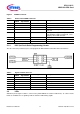
Figure 7 LEDs Circuit
Table 6 LEDs Signal Description
LED Designation
Signal Name
Description
LED102
P0.7
Output ‘High’ to on LED
LED103
P0.5
Output ‘Low’ to on LED
LED104
P0.6
Output ‘Low’ to on LED
LED105
P1.2
Output ‘Low’ to on LED
LED106
P1.3
Output ‘Low’ to on LED
LED107
P1.4
Output ‘Low’ to on LED
LED108
P1.5
Output ‘Low’ to on LED
2.3 Other connectors
XMC1100 microcontroller has more pins than is required Arduino
TM
board’s pinouts, those extra pins are group
into connector AD_AUX (not mount) and AUX (not mount).
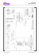
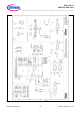
Figure 8 AD_AUX and AUX connector