
User manual

CPU-11A-V1
XMC1100 CPU Card
Board User's Manual 9 Revision 2.0, 2013-12-18
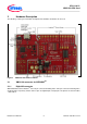
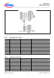
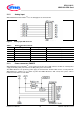
Figure 3 Digital IO connectors IOH, IOL
Table 1 Digital IO of connector IOH
Pin No.
Arduino
TM
Signal Name
XMC1100 Signal Name
Description
10
SCL
P2.0
I
2
C Clock
9
SDA
P2.1
I
2
C Data / Address
8
AREF
P2.3
Analog reference voltage
7
GND
GND
Ground
6
13 - SCK
P0.7
SPI-SCK / LED output
5
12 - MISO
P1.0
SPI-MISO
4
~11 - MOSI
P1.1
SPI-MOSI / PWM output
3
~10 - SS
P0.9
SPI-SS / PWM output
2
~9 -
P0.8
PWM output
1
8
P0.12
GPIO
Table 2 Digital IO of connector IOL
Pin No.
Arduino
TM
Signal Name
XMC1100 Signal Name
Description
8
7
P0.4
GPIO
7
~6
P0.3
PWM output
6
~5
P0.2
PWM output
5
4
P0.1
GPIO
4
~3
P0.0
External interrupt / PWM output
3
2
P1.4
External interrupt
2
1 - TX(IN)
P1.3
Device received UART signal
1
0 - RX(OUT)
P1.2
Device transmit UART signal