X MC12 00 CPU Car d For XMC1000 Family CPU- 12A- V1 XMC1200 CPU Card Boar d User ' s Manu a l Revision 2.
Edition 2013-12-18 Published by Infineon Technologies AG 81726 Munich, Germany © 2013 Infineon Technologies AG All Rights Reserved. Legal Disclaimer The information given in this document shall in no event be regarded as a guarantee of conditions or characteristics.
CPU-12A-V1 XMC1200 CPU Card Revision History Page or Item Subjects (major changes since previous revision) Revision 2.0, 2013-12-18 14, 15 Change C210 to 4.
CPU-12A-V1 XMC1200 CPU Card Table of Contents 1 1.1 1.2 Overview ........................................................................................................................................ 7 Key Features .................................................................................................................................. 7 Block Diagram................................................................................................................................. 7 2 2.1 2.2 2.
CPU-12A-V1 XMC1200 CPU Card List of Figures Figure 1 Figure 2 Figure 3 Figure 4 Figure 5 Figure 6 Figure 7 Figure 8 Figure 9 Block Diagram of XMC1200 CPU Card............................................................................................ 7 XMC1200 CPU Card ....................................................................................................................... 8 Power Supply circuit .................................................................................................
CPU-12A-V1 XMC1200 CPU Card List of Tables Table 1 Table 2 Table 3 Debug connector X201 .................................................................................................................... 9 LEDs Pinout .................................................................................................................................. 10 XMC1200 CPU Card .....................................................................................................................
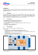
CPU-12A-V1 XMC1200 CPU Card Introduction This document describes the features and hardware details of the XMC1200 CPU Card. This board is mounted ® TM with ARM Cortex -M0 based XMC1200 Microcontroller from Infineon Technologies AG and part of Infineon’s XMC1000 offering of Kits 1 Overview The XMC1200 CPU Card (CPU-12A-V1) houses the XMC1200 Microcontroller and a 2x30 pin edge for application expansion. This board along with application cards (e.g.
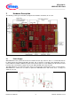
CPU-12A-V1 XMC1200 CPU Card 2 Hardware Description The following sections give a detailed description of the hardware and how it can be used. Figure 2 2.1 XMC1200 CPU Card Power Supply XMC1200 CPU Card is powered from the micro USB connector (5V); however, there is a current limit that can be drawn from the host PC through USB. If the CPU_12A_V1 board is used to drive other application card (e.g.
CPU-12A-V1 XMC1200 CPU Card 2.2 Reset XMC1200 does not have a reset pin, hence, user needs to unplug and replug the USB cable to achieve poweron with master reset to the XMC1200 device. 2.3 Clock Generation No external clock source is required. XMC1200 has two internal oscillators DCO1 and DCO2. DCO1 has a clock output of 64MHz. DCO2 is used to generate the standby clock running at 32.768KHz which used for Real Time Clock too.
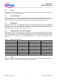
CPU-12A-V1 XMC1200 CPU Card Figure 4 Table 2 LEDs circuit LEDs Pinout LED XMC1200 Port Pin Description LED101 LED102 LED103 LED104 LED105 P0.0 P0.2 P0.5 P0.6 P0.7 Output ‘Low’ to on LED Output ‘Low’ to on LED Output ‘Low’ to on LED Output ‘Low’ to on LED Output ‘Low’ to on LED 2.7 Potentiometer XMC1200 CPU Card provides a potentiometer R110 for ease of use and testing of the on-chip analog to digital converter. The potentiometer is connected to the analog input P2.5.
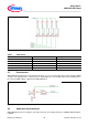
CPU-12A-V1 XMC1200 CPU Card Figure 6 Pinout of the 2x30 pin edge connector Board User's Manual 11 Revision 2.
CPU-12A-V1 XMC1200 CPU Card 3 Production Data 3.1 Schematics This chapter contains the schematics for the XMC1200 CPU Card: Figure 7: CPU, Pin Headers, Potentiometer and LED and 60pin Edge connector Figure 8: On-board Debugger, Power Supply Board User's Manual 12 Revision 2.
CPU-12A-V1 XMC1200 CPU Card Figure 7 Schematic 1 of 2 XMC1200 CPU Card Board User's Manual 13 Revision 2.
CPU-12A-V1 XMC1200 CPU Card Figure 8 Schematic 2 of 2 XMC1200 CPU Card Board User's Manual 14 Revision 2.
CPU-12A-V1 XMC1200 CPU Card 3.2 Layout and Geometry Figure 9 XMC1200 CPU Card layout and geometry 3.3 Bill of Material Table 3 XMC1200 CPU Card No.
CPU-12A-V1 XMC1200 CPU Card No.
CPU-12A-V1 XMC1200 CPU Card No. Qty Value Device Reference Designator 60 61 62 63 1 1 1 1 LED-GN/D/0603 LED-R/D/0603 ESD8V0L2B-03L ZX62-AB-5PA ChipLED ChipLED Diode Micro-USB V201 V202 V204 X202 64 1 XMC1200-T038 65 1 IFX25001MEV33 66 1 67 68 69 70 71 72 1 1 1 1 1 1 73 74 75 1 1 1 XMC4200_QFN48 BAT60A BRIDGE10X10 BRIDGE10X10 no ass./10nF/0402 no ass./MCU no ass./MCU no ass./MCU no ass./MCU no ass.
w w w . i nf i n eo n.