
User manual

CPU-12A-V1
XMC1200 CPU Card
Board User's Manual 10 Revision 2.0, 2013-12-18
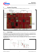
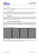
Figure 4 LEDs circuit
Table 2 LEDs Pinout
LED
XMC1200 Port Pin
Description
LED101
P0.0
Output ‘Low’ to on LED
LED102
P0.2
Output ‘Low’ to on LED
LED103
P0.5
Output ‘Low’ to on LED
LED104
P0.6
Output ‘Low’ to on LED
LED105
P0.7
Output ‘Low’ to on LED
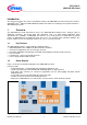
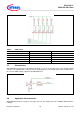
2.7 Potentiometer
XMC1200 CPU Card provides a potentiometer R110 for ease of use and testing of the on-chip analog to digital
converter. The potentiometer is connected to the analog input P2.5. The analog output of the potentiometer is
the same the VDDP voltage supplied to the XMC1200 device.
Figure 5 Potentiometer Circuit
2.8 Application Card connector
XMC1200 CPU Card has a 2x30 pins card edge connector. The mating connector is SAMTEC HSEC8-130-01-
L-RA-XX.