
User manual

CPU-12A-V1
XMC1200 CPU Card
Board User's Manual 7 Revision 2.0, 2013-12-18
Introduction
This document describes the features and hardware details of the XMC1200 CPU Card. This board is mounted
with ARM
®
Cortex
TM
-M0 based XMC1200 Microcontroller from Infineon Technologies AG and part of Infineon’s
XMC1000 offering of Kits
1 Overview
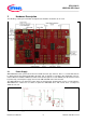
The XMC1200 CPU Card (CPU-12A-V1) houses the XMC1200 Microcontroller and a 2x30 pin edge for
application expansion. This board along with application cards (e.g. LED Lighting Application Card)
demonstrates the capabilities of XMC1200. The main use case for this board is to demonstrate the generic
features of XMC1200 device including tool chain. The focus is safe operation under evaluation conditions. The
board is neither cost nor size optimized and does not serve as a reference design.
1.1 Key Features
The XMC1200 CPU Card is equipped with the following features:
XMC1200 (ARM
®
Cortex
TM
-M0 based) Microcontroller, TSSOP38
Connection to application cards via card edge connector
Detachable SEGGER J-Link debugger and UART virtual COM port, with micro USB connector
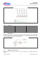
Five user LEDs
Potentiometer, connected to analog input P2.5
Power supply via Micro-USB connector
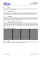
1.2 Block Diagram
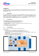
Figure 1 shows the functional block diagram of the XMC1200 CPU Card.
Features include:
− On board Debugger, for downloading and debugging of application code
− Virtual com port for uart communication with terminal program e.g. Hyperterminal.
− 2x30 Card edge connector, for extension to application card e.g. LED Lighting and Motor Control
Application Card.
− 5 User LEDs connected to GPIO P0.0, P0.2, P0.5, P0.6, P0.7
− Variable resistor R110 connected to Analog input P2.5
− All the pins of XMC1200 are accessible via the connector JP101, JP102, JP103 and JP104
Figure 1 Block Diagram of XMC1200 CPU Card