
Datasheet

C161K
C161O
Data Sheet 9 V2.0, 2001-01
Functional Description
The architecture of the C161K/O combines advantages of both RISC and CISC
processors and of advanced peripheral subsystems in a very well-balanced way. In
addition the on-chip memory blocks allow the design of compact systems with maximum
performance.
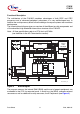
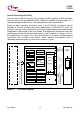
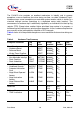
The following block diagram gives an overview of the different on-chip components and
of the advanced, high bandwidth internal bus structure of the C161K/O.
Note: All time specifications refer to a CPU clock of 25 MHz
(see definition in the AC Characteristics section).
Figure 3 Block Diagram
The program memory, the internal RAM (IRAM) and the set of generic peripherals are
connected to the CPU via separate buses. A fourth bus, the XBUS, connects external
resources as well as additional on-chip resources, the X-Peripherals (see Figure 3).
C166-Core
MCB04323_1ko
CPU
Port 2
Interrupt Bus
XTAL
Osc
WDT
32
16
Interrupt Controller
16-Level
Priority
PEC
External Instr. / Data
GPT1
T2
T3
T4
SSC
BRGen
(SPI)
ASC0
BRGen
(USART)
EBC
XBUS Control
External Bus
Control
IRAM
Dual Port
Internal
RAM
1/2 Kbyte
ProgMem
Internal
ROM
Area
Data
Data
16
16
16
Port 0
Port 6
8
8
Port 1
16
6
16
Port 5Port 3
15
Port 4
8
16
Instr. / Data
O
n
-C
h
ip
X
B
U
S
(1
6
-B
it D
e
m
u
x)
Peripheral Data Bus
GPT2
T5
T6