
Datasheet

C505/C505C/C505A/C505CA
Data Sheet 42 12.00
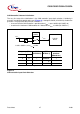
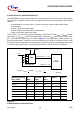
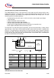
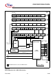
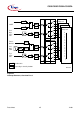
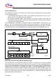
Interrupt System
The C505 provides 12 interrupt vectors with four priority levels. Five interrupt requests can be
generated by the on-chip peripherals (timer 0, timer 1, timer 2, serial interface, A/D converter). One
interrupt can be generated by the CAN controller (C505C and C505CA only) or by a software setting
and in this case the interrupt vector is the same. Six interrupts may be triggered externally (P3.2/
INT0
, P3.3/INT1, P1.0/AN0/INT3/CC0, P1.1/AN1/INT4/CC1, P1.2/AN2/INT5/CC2, P1.3/AN3/INT6/
CC3). Additionally, the P1.5/AN5/T2EX can trigger an interrupt. The wake-up from power-down
mode interrupt has a special functionality which allows to exit from the software power-down mode
by a short low pulse at either pin P3.2/INT0
or the pin P4.1/RXDC.
Figure 21 to Figure 23 give a general overview of the interrupt sources and illustrate the request
and the control flags which are described in the next sections. Table 9 lists all interrupt sources with
their request flags and interrupt vector addresses.
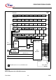
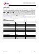
Table 9
Interrupt Source and Vectors
Interrupt Source Interrupt Vector Address Interrupt Request Flags
External Interrupt 0 0003
H
IE0
Timer 0 Overflow 000B
H
TF0
External Interrupt 1 0013
H
IE1
Timer 1 Overflow 001B
H
TF1
Serial Channel 0023
H
RI / TI
Timer 2 Overflow / Ext. Reload 002B
H
TF2 / EXF2
A/D Converter 0043
H
IADC
CAN Controller / Software Interrupt 004B
H
– / SWI
External interrupt 3 0053
H
IEX3
External Interrupt 4 005B
H
IEX4
External Interrupt 5 0063
H
IEX5
External interrupt 6 006B
H
IEX6
Wake-up from power-down mode 007B
H
–