
Datasheet


C515C
Data Sheet 11 2003-02
HWPD
69 I Hardware Power Down
A low level on this pin for the duration of one
machine cycle while the oscillator is running resets
the C515C.
A low level for a longer period will force the part to
power down mode with the pins floating.
P4.0-P4.7 72-74, 76-80
72
73
74
76
77
78
79
80
I/O Port 4
is an 8-bit quasi-bidirectional I/O port with internal
pull-up resistors. Port 4 pins that have 1’s written to
them are pulled high by the internal pull-up resistors,
and in that state can be used as inputs. As inputs,
port 4 pins being externally pulled low will source
current (
I
IL
, in the DC characteristics) because of
the internal pull-up resistors.
P4 also contains the external A/D converter control
pin, the SSC pins, the CAN controller input/output
lines, and the external interrupt 8 input. The output
latch corresponding to a secondary function must
be programmed to a one (1) for that function to
operate. The alternate functions are assigned to
port 4 as follows:
P4.0 ADST
External A/D converter start pin
P4.1 SCLK SSC Master Clock Output /
SSC Slave Clock Input
P4.2 SRI SSC Receive Input
P4.3 STO SSC Transmit Output
P4.4 SLS
Slave Select Input
P4.5 INT8
External interrupt 8 input
P4.6 TXDC Transmitter output of the CAN
controller
P4.7 RXDC Receiver input of the CAN controller
Table 2 Pin Definitions and Functions (cont’d)
Symbol Pin Number I/O
1)
Function
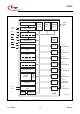
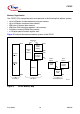
P-MQFP-80-1