
Datasheet


XC164-32
Derivatives
General Device Information
Data Sheet 13 V1.1, 2006-08
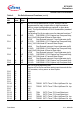
P20
P20.0
P20.1
P20.4
P20.5
P20.12
63
64
65
66
2
IO
O
O
O
I
O
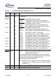
Port 20 is a 5-bit bidirectional I/O port. Each pin can be
programmed for input (output driver in high-impedance
state) or output. The input threshold of Port 20 is selectable
(standard or special).
The following Port 20 pins also serve for alternate functions:
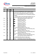
RD
External Memory Read Strobe, activated for
every external instruction or data read access.
WR
/WRL External Memory Write Strobe.
In WR
-mode this pin is activated for every
external data write access.
In WRL
-mode this pin is activated for low byte
data write accesses on a 16-bit bus, and for
every data write access on an 8-bit bus.
ALE Address Latch Enable Output.
Can be used for latching the address into
external memory or an address latch in the
multiplexed bus modes.
EA
External Access Enable pin.
A low level at this pin during and after Reset
forces the XC164CS to latch the configuration
from PORT0 and pin RD
, and to begin
instruction execution out of external memory.
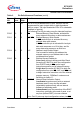
A high level forces the XC164CS to latch the
configuration from pins RD
, ALE, and WR, and
to begin instruction execution out of the internal
program memory. “ROMless” versions must
have this pin tied to ‘0’.
RSTOUT
Internal Reset Indication Output.
Is activated asynchronously with an external
hardware reset. It may also be activated
(selectable) synchronously with an internal
software or watchdog reset.
Is deactivated upon the execution of the EINIT
instruction, optionally at the end of reset, or at
any time (before EINIT) via user software.
Note: Port 20 pins may input configuration values (see EA
).
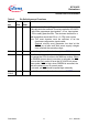
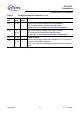
Table 2 Pin Definitions and Functions (cont’d)
Sym-
bol
Pin
Num.
Input
Outp.
Function