
Datasheet


XC164-32
Derivatives
General Device Information
Data Sheet 16 V1.1, 2006-08
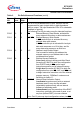
V
DDI
35, 97 – Digital Core Supply Voltage (On-Chip Modules):
+2.5 V during normal operation and idle mode.
Please refer to the Operating Condition Parameters.
V
DDP
9, 17,
38, 61,
87
– Digital Pad Supply Voltage (Pin Output Drivers):
+5 V during normal operation and idle mode.
Please refer to the Operating Condition Parameters.
V
SSI
34, 98 – Digital Ground
Connect decoupling capacitors to adjacent
V
DD
/V
SS
pin pairs
as close as possible to the pins.
All
V
SS
pins must be connected to the ground-line or ground-
plane.
V
SSP
8, 16,
37, 62,
88
–
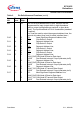
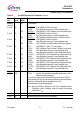
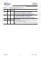
1) The CAN interface lines are assigned to ports P4 and P9 under software control.
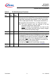
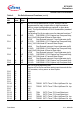
Table 2 Pin Definitions and Functions (cont’d)
Sym-
bol
Pin
Num.
Input
Outp.
Function