
Datasheet

XC164-32
Derivatives
Electrical Parameters
Data Sheet 52 V1.1, 2006-08
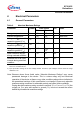
Operating Conditions
The following operating conditions must not be exceeded to ensure correct operation of
the XC164CS. All parameters specified in the following sections refer to these operating
conditions, unless otherwise noticed.
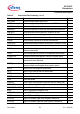
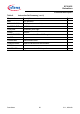
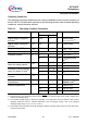
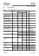
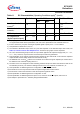
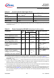
Table 10 Operating Condition Parameters
Parameter Symbol Limit Values Unit Notes
Min. Max.
Digital supply voltage for
the core
V
DDI
2.35 2.7 V Active mode,
f
CPU
= f
CPUmax
1)2)
1) f
CPUmax
= 40 MHz for devices marked … 40F, f
CPUmax
= 20 MHz for devices marked … 20F.
2) External circuitry must guarantee low-level at the RSTIN
pin at least until both power supply voltages have
reached the operating range.
Digital supply voltage for
IO pads
V
DDP
4.4 5.5 V Active mode
2)3)
3) The specified voltage range is allowed for operation. The range limits may be reached under extreme
operating conditions. However, specified parameters, such as leakage currents, refer to the standard
operating voltage range of
V
DDP
= 4.75 V to 5.25 V.
Supply Voltage Difference ∆V
DD
-0.5 – V V
DDP
- V
DDI
4)
4) This limitation must be fulfilled under all operating conditions including power-ramp-up, power-ramp-down,
and power-save modes.
Digital ground voltage V
SS
0 V Reference voltage
Overload current
I
OV
-5 5 mA Per IO pin
5)6)
-2 5 mA Per analog input
pin
5)6)
Overload current coupling
factor for analog inputs
7)
K
OVA
–1.0 × 10
-4
– I
OV
> 0
–1.5 × 10
-3
– I
OV
< 0
Overload current coupling
factor for digital I/O pins
7)
K
OVD
–5.0 × 10
-3
– I
OV
> 0
–1.0 × 10
-2
– I
OV
< 0
Absolute sum of overload
currents
Σ|
I
OV
|– 50 mA
6)
External Load
Capacitance
C
L
– 50 pF Pin drivers in
default mode
8)
Ambient temperature T
A
070°C SAB-XC164…
-40 85 °C SAF-XC164…
-40 125 °C SAK-XC164…