
Datasheet


C167CR
C167SR
General Device Information
Data Sheet 25 V3.3, 2005-02
Note: The following behavioural differences must be observed when the bidirectional
reset is active:
• Bit BDRSTEN in register SYSCON cannot be changed after EINIT and is cleared
automatically after a reset.
• The reset indication flags always indicate a long hardware reset.
• The PORT0 configuration is treated as if it were a hardware reset. In particular, the
bootstrap loader may be activated when P0L.4 is low.
•Pin RSTIN
may only be connected to external reset devices with an open drain output
driver.
• A short hardware reset is extended to the duration of the internal reset sequence.
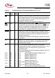
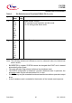
V
DD
B8,
C12,
D14,
F1,
H3,
H14,
K4,
M5,
M12,
P8
– Digital Supply Voltage:
+ 5 V during normal operation and idle mode.
≥ 2.5 V during power down mode.
V
SS
A8,
D11,
E1,
E12,
G12,
H2,
L3,
L5,
L11,
M8
– Digital Ground.
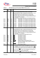
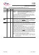
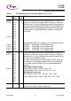
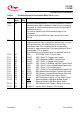
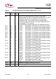
Table 3 Pin Definitions and Functions P-BGA-176-2 (cont’d)
Symbol Pin
Num.
Input
Outp.
Function