
Datasheet

C167CR
C167SR
Electrical Parameters
Data Sheet 60 V3.3, 2005-02
Parameter Interpretation
The parameters listed in the following partly represent the characteristics of the C167CR
and partly its demands on the system. To aid in interpreting the parameters right, when
evaluating them for a design, they are marked in column “Symbol”:
CC (Controller Characteristics):
The logic of the C167CR will provide signals with the respective timing characteristics.
SR (System Requirement):
The external system must provide signals with the respective timing characteristics to
the C167CR.
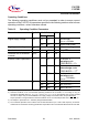
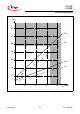
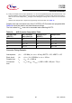
4.2 DC Parameters
Table 11 DC Characteristics (Operating Conditions apply)
1)
Parameter Symbol Limit Values Unit Test Condition
Min. Max.
Input low voltage (TTL,
all except XTAL1)
V
IL
SR -0.5 0.2 V
DD
- 0.1
V–
Input low voltage XTAL1
V
IL2
SR -0.5 0.3 V
DD
V–
Input low voltage
(Special Threshold)
V
ILS
SR -0.5 2.0 V –
Input high voltage (TTL,
all except RSTIN
and XTAL1)
V
IH
SR 0.2 V
DD
+ 0.9
V
DD
+
0.5
V–
Input high voltage RSTIN
(when operated as input)
V
IH1
SR 0.6 V
DD
V
DD
+
0.5
V–
Input high voltage XTAL1
V
IH2
SR 0.7 V
DD
V
DD
+
0.5
V–
Input high voltage
(Special Threshold)
V
IHS
SR 0.8 V
DD
- 0.2
V
DD
+
0.5
V–
Input Hysteresis
(Special Threshold)
HYS 400 – mV Series
resistance = 0 Ω
Output low voltage
(PORT0, PORT1, Port 4, ALE,
RD
, WR, BHE, CLKOUT,
RSTOUT
, RSTIN
2)
)
V
OL
CC – 0.45 V I
OL
= 2.4 mA
Output low voltage
(all other outputs)
V
OL1
CC – 0.45 V I
OL
= 1.6 mA