Data Sheet, V1.5, Nov. 2007 Uni- and Bipolar Hall IC Switches for Magnetic Field Applications TLE4905L, TLE4935L, TLE4945L, TLE4945-2L Sensors N e v e r s t o p t h i n k i n g .
Edition 2007-11 published by Infineon Technologies AG, Am Campeon 1-12, 81726 München, Germany © Infineon Technologies AG 2007. All Rights Reserved. Attention please! The information herein is given to describe certain components and shall not be considered as a guarantee of characteristics. Terms of delivery and rights to technical change reserved.
Uni- and Bipolar Hall IC Switches for Magnetic Field Applications TLE4905L, TLE4935L, TLE4945L, TLE4945-2L Features • • • • • • Digital output signal For unipolar and alternating magnetic fields Large temperature range Temperature compensated magnetic performance Protection against reversed polarity Output protection against electrical disturbances PG-SSO-3-2 P-SSO-3-2 Type Marking Package TLE4905L 05 L PG-SSO-3-2 TLE4935L 35 L PG-SSO-3-2 TLE4935-2L 35 2 PG-SSO-3-2 TLE4945L 45 L PG-SSO-3-2
TLE4905L, TLE4935L, TLE4945L, TLE4945-2L Pin Configuration (view on branded side of component) Center of sensitive area 1.35 ±0.1 2.08 ±0.1 1 VS 2 3 GND Q AEP01364 Figure 1 Pin Definitions and Functions Pin No. Symbol Function 1 VS Supply voltage 2 GND Ground 3 Q Output Data Sheet 2 V1.
TLE4905L, TLE4935L, TLE4945L, TLE4945-2L Circuit Description The circuit includes Hall generator, amplifier and Schmitt-Trigger on one chip. The internal reference provides the supply voltage for the components. A magnetic field perpendicular to the chip surface induces a voltage at the hall probe. This voltage is amplified and switches a Schmitttrigger with open-collector output. A protection diode against reverse power supply is integrated. The output is protected against electrical disturbances.
TLE4905L, TLE4935L, TLE4945L, TLE4945-2L Functional Description Unipolar Type TLE4905 (Figure 3 and 4) When a positive magnetic field is applied in the indicated direction (Figure 3) and the turn-on magnetic induction BOP is exceeded, the output of the Hall-effect IC will conduct (Operate Point). When the current is reduced, the output of the IC turns off (Release Point; Figure 4).
TLE4905L, TLE4935L, TLE4945L, TLE4945-2L Functional Description Bipolar Type TLE4935/45/45-2 (Figure 5 and 6) When a positive magnetic field is applied in the indicated direction (Figure 5) and the turn-on magnetic induction BOP is exceeded, the output of the Hall-effect IC will conduct (Operate Point). The output state does not change unless a reverse magnetic field exceeding the turn-off magnetic iinduction BRP is exceeded. In this case the output will turn off (Release Point; Figure 6).
TLE4905L, TLE4935L, TLE4945L, TLE4945-2L Absolute Maximum Ratings Tj = – 40 to 150 °C Parameter Supply voltage Supply voltage Output voltage Output current Output reverse current Junction temperature Junction temperature Junction temperature Storage temperature Thermal resistance Symbol VS VS VQ IQ – IQ Tj Tj Tj Tstg Rth JA Limit Values Unit Remarks min. max. – 40 32 V – – 40 V t < 400 ms; ν = 0.
TLE4905L, TLE4935L, TLE4945L, TLE4945-2L AC/DC Characteristics 3.8 V ≤ VS ≤ 24 V; – 40 °C ≤ Tj ≤ 150 °C Parameter Symbol Limit Values Unit Test Condition Test Circuit min. typ. max. ISHigh ISLow VQSat – – 3 4 7 8 mA mA B < BRP B > BOP 1 1 – 0.25 0.5 V IQ = 40 mA 1 Output leakage current IQL – – 10 µA VQ = 24 V 1 Rise/fall time tr / tf – – 1 µs RL = 1.
TLE4905L, TLE4935L, TLE4945L, TLE4945-2L Magnetic Characteristics 3.8 V ≤ VS ≤ 24 V Parameter Symbol Limit Values TLE4905 unipolar min. max. TLE4935 bipolar latch min. Unit TLE4945 bipolar switch TLE4945-2 bipolar switch max. min. max. min. max. Junction Temperature Tj = – 40 °C Turn-ON induction Turn-OFF induction Hysteresis (BOP – BRP) BOP 7.5 19 10 20 –6 10 –3 6 mT BRP 5.5 17 – 20 – 10 – 10 6 –6 3 mT ∆BH 2 6.
TLE4905L, TLE4935L, TLE4945L, TLE4945-2L Magnetic Characteristics (cont’d) 3.8 V ≤ VS ≤ 24 V Parameter Symbol Limit Values TLE4905 unipolar min. max. TLE4935 bipolar latch Unit TLE4945 bipolar switch TLE4945-2 bipolar switch min. max. min. max. min. max.
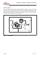
TLE4905L, TLE4935L, TLE4945L, TLE4945-2L VS ΙS 1 + VS 4.7 nF - 2 RL TLE 4905/35/35-2/45-2 GND CL 3 ΙQ Q AES01244 Unipolar Type TLE4905 Bipolar Type TLE4935 VQ VQ VQH VQH VQL VQL 0 B RP B OP B B RP B HY B B OP 0 B HY AED01422 AED01426 8 B _V _ 24 V < 3.8 V < S mT 6 B HYmax 4 B HYtyp 2 0 -40 B HYmin 0 50 100 200 ˚C Tj Figure 7 Data Sheet Test Circuit 1 10 V1.
TLE4905L, TLE4935L, TLE4945L, TLE4945-2L Mainframe Line Sensor 1 VS VS 4.7 nF 2 1.2 k Ω GND TLE 4905/35/35-2/45-2 4.7 nF 3 Signal Q AES01247 Figure 8 Data Sheet Application Circuit 11 V1.
TLE4905L, TLE4935L, TLE4945L, TLE4945-2L If not otherwise specified, all curves reflect typical values at Tj = 25 °C and VS = 12 V Quiescent Current versus Supply Voltage ΙS Quiescent Current versus Junction Temperature AED01248 8 ΙS mA AED01249 8 mA VQ = High VQ = High 6 6 4 T j = -40 ˚C 4 VS = 24 V T j = 150 ˚C VS = 4.0 V 2 2 0 -50 0 5 0 10 15 25 V 0 50 100 Tj Quiescent Current Difference versus Temperature Saturation Voltage versus Output Current AED01459 1.
TLE4905L, TLE4935L, TLE4945L, TLE4945-2L TLE4905 Operate-and Release-Point versus Junction Temperature AED03289 25 B TLE4905 Hysteresis versus Junction Temperature B 3.8 V <_ VS <_ 24 V mT AED03290 8 3.8 V <_ VS <_ 24 V mT 20 6 B OPmax B HYmax 15 B RPmax 4 10 2 B OPmin 5 B HYmin B RPmin 0 -40 0 50 100 0 -40 200 ˚C 0 50 100 Tj TLE4945 Operate-and Release-Point versus Junction Temperature TLE4935 Operate-and Release-Point versus Junction Temperature AED03291 30 B B 3.
TLE4905L, TLE4935L, TLE4945L, TLE4945-2L TLE4945-2 Operate-and Release-Point versus Junction Temperature AED03294 18 B 3.
TLE4905L, TLE4935L, TLE4945L, TLE4945-2L Package Outlines PG-SSO-3-2 (Plastic Single Small Outline Package) 0.8 ±0.1 x 45° 7° 0.2 2 A 1.52±0.05 1) 1 MAX. 7° 0.35 ±0.1 x 45° 3 ±0.06 1 .9 MAX. 3.29±0.08 4.06±0.08 (0.25) 0.15 MAX. 4.16±0.05 (0.79) 0.6 MAX. 0.2 +0.1 0.4 ±0.05 1.27±0.25 1 2 3 1.27±0.25 18±0.5 6 ±0.5 1-1 38 MAX. 9 -0.5 +0.75 23.8 ±0.5 12.7±1 A Adhes iv e Tape Tape 6.35±0.4 4 ±0.3 0.39 ±0.1 12.7±0.3 1) N o s older func tion area Data Sheet 0.25-0.
TLE4905L, TLE4935L, TLE4945L, TLE4945-2L d Branded Side Hall-Probe d : Distance chip to branded side of IC P-SSO-3-2 : 0.57 ±0.08 mm AEA02510 You can find all of our packages, sorts of packing and others in our Infineon Internet Page “Products”: http://www.infineon.com/products. Data Sheet 16 Dimensions in mm V1.
TLE4905L, TLE4935L, TLE4945L, TLE4945-2L Revision History: 2007-11, V1.5 Previous Version: V1.4:§ Page Subjects (major changes since last revision) Package changed to PG-SSO-3-2 For questions on technology, delivery and prices please contact the Infineon Technologies offices in Germany or the Infineon Technologies Companies and Representatives worldwide: see our webpage at http://www.infineon.
w w w . i n f i n e o n .