
Datasheet


TLE6251D
Functional Description
Data Sheet 10 Rev. 1.0, 2012-07-27
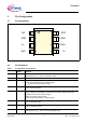
4.6 Remote Wake-up
The TLE6251D has a remote wake-up feature, also called bus wake-up feature. In stand-by mode, the low-power
receiver monitors the activity on the CAN bus and in case it detects a wake-up signal, the TLE6251D indicates the
wake-up signal on the RxD output pin.
While entering into stand-by mode by setting the STB pin to logical “high”, the RxD output pin is set to logical “high”,
regardless of the signal on the CAN bus. The low-power receiver of the TLE6251D requires a signal change from
“recessive” to “dominant” on the CAN bus before the RxD output is enabled and follows the signal on the CAN bus.
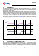
CAN bus signals, “dominant” or “recessive”, with a pulse width above the bus wake-up time t >
t
WU
are indicated
on the RxD output pin (see Figure 5).
The wake-up logic is supplied by the power supply
V
IO
(see Figure 1). In case the TLE6251D is in stand-by mode,
the power supply
V
CC
can be turned off, while the TLE6251D is still able to detect the wake-up pattern on the CAN
bus.
Figure 5 Wake-up pattern
4.7 Voltage Adaption to the Microcontroller Supply
The HS CAN transceiver TLE6251D has two different power supplies, V
CC
and V
IO
. The power supply V
CC
supplies
the transmitter and the normal mode receiver, the power supply
V
IO
supplies the digital input and output buffers,
the low-power receiver and the wake-up logic. To adjust the digital input and output levels of the TLE6251D to the
I/O levels of the external microcontroller, the power supply
V
IO
should be connected to the microcontroller pad
supply (see Figure 13).
Supplying the low-power receiver by the
V
IO
pin allows to switch off the V
CC
supply in stand-by mode and leads to
an additional reduction of the quiescent current in stand-by mode.
RxD
t
t
CANH
CANL
STB
t
t
V
DIFF
t = t
WU
t = t
WU
V
IO
t = t
WU
V
DIFF
= CANH - CANL
t = t
WU