
Datasheet


TLE6251D
Functional Description
Data Sheet 8 Rev. 1.0, 2012-07-27
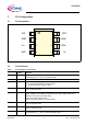
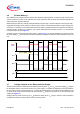
4.2 Modes of Operation
Two different modes of operation are available on the TLE6251D. Each mode has specific characteristics in terms
of quiescent current or data transmission. The digital input pin STB is used for the mode selection. Figure 4
illustrates the different mode changes depending on the status of the STB pin. After supplying
V
CC
and V
IO
to the
HS CAN transceiver, the TLE6251D starts in stand-by mode. The internal pull-up resistor at the STB pin sets the
TLE6251D to stand-by mode by default. If the microcontroller is up and running, the TLE6251D can switch to any
operating mode within the time period for mode change
t
MODE
.
Figure 4 Mode of operation
The TLE6251D has 2 major modes of operation:
• Stand-by mode
• Normal-operating mode
undervoltage
detection on V
CC
and
V
IO
power-down
V
CC
< V
CC(UV)
start–up
supply V
CC
and
V
IO
V
IO
< V
IO(UV)
STB = 0
normal-operating
mode
STB = 1
stand-by mode
STB = 0 STB = 1
Table 2 Modes of Operation
Mode STB Bus Bias Comment
Normal-
operating mode
“low”
V
CC
/2 The transmitter is active.
The normal mode receiver is active.
The low-power receiver is disabled.
Stand-by mode
V
CC
on
V
IO
on
“high”
GND The transmitter is disabled.
The normal mode receiver is disabled.
The low-power receiver is active.
Stand-by mode
V
CC
off
V
IO
on
“high” GND The transmitter is disabled.
The normal mode receiver is disabled.
The low-power receiver is active.
Power-down
state
V
CC
off
V
IO
off
Don’t care Floating The transmitter is disabled.
The normal mode receiver is disabled.
The low-power receiver is disabled.