
User's Manual


InfiNet Wireless R5000 Technical User Manual
Copyright © 2004-2011 by InfiNet Wireless
55
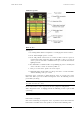
LEDs Function
1. Power/ODU
connection LED
Shows diagnostic device power status and diagnostic device-ODU connection status.
Constant lighting — diagnostic device-ODU connection established, diagnostic device power is
normal.
Blinking 1 time per second
— diagnostic device power is normal, diagnostic device-ODU
connection is not established.
Blinking 4 times per second
— diagnostic device-ODU connection established, diagnostic
device power is low (change batteries).
Frequent blinking with intervals
— diagnostic device power is low, diagnostic device-ODU
connection is not established.
2. Radio link LEDs Show whether radio link is established on certain ODU’s radio interface.
Constant lighting
— radio link is established.
What ODU’s radio interface to show by what column RF0 or RF1 is chosen by the following
way:
for RF0 column is taken radio interface with the least number, for RF1 the other interface.
For example, there are the following radio interfaces on ODU:
Rf5.0, rf5.1. Then for RF0 column rf5.0 will be taken, for RF1 — rf5.1.
When no radio link then LEDs 2-4 are not lighting.
3. Radio signal
overload/Packets
retries LEDs
Show receiving radio signal level overload and number of packet retries information.
Constant lighting
—receiving radio signal level on the interface is too high.
Blinking 4 times per second
- number of retries >= 50%
Blinking 2 times per second
- number of retries >= 28 %
Blinking 1 time per second
- number of retries >= 7 %
If certain radio interface (radio module) is not present on the device then all corresponding
LEDs of this radio interface is off.
If ODU has certain radio interface but it is not activated (for example, not entered «mint rf5.0
start» command) then LED 3 is blinking 1 time per second whereas LEDs 2 and 4 are not
lighting.
If ODU has certain radio interface but it is not activated (for example, not entered «mint rf5.0
start» command) then LED 3 is blinking 1 time per second whereas LEDs 2 and 4 are not
lighting.
If ODU has certain radio interface activated («mint rf5.0 start» command entered) then LED 3
is blinking 4 times per second whereas LEDs 2 and 4 are not lighting.
4. Radio signal level
scales
Show receiving signal level of the established radio link.
Each LED can be in 4 modes:
Not lighting
— radio signal level is lower than scale value.
Blinking
— the more frequently is blinking the nearer signal level is to given scale value.
Constant lighting
— signal level is higher or equal to scale value.
5. Ethernet interface
data rate LEDs
Show data rate of the corresponding Ethernet interface.
There are 2 LEDs for each Ethernet interface (Eth0 and Eth1).
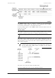
10 Mbps 100 Mbps 1000 Mbps Error
Upper LED Lighting Not lighting Lighting Blinking
Lower LED Not lighting Lighting Lighting Blinking
6. Ethernet interface
mode LEDs
Constant lighting — Full Duplex.
Not lighting
— Half Duplex.
IF Ethernet connection is established but corresponding ODU’s interface is not enabled then
LEDs 5, 6 indicate connection configuration by blinking 1 time per second.