Printing: February 2011 (11) / OM1E 0J50U2 / Printed in U.S.A. 2011 Infiniti EX For your safety, read carefully and keep in this vehicle.
FOREWORD Your INFINITI represents a new way of thinking about vehicle design. It integrates advanced engineering and superior craftsmanship with a simple, refined aesthetic sensitivity associated with traditional Japanese culture. The result is a different notion of luxury and beauty.
MODIFICATION OF YOUR VEHICLE This vehicle should not be modified. Modification could affect its performance, safety or durability, and may even violate governmental regulations. In addition, damage or performance problems resulting from modification will not be covered under the INFINITI warranties. WHEN READING THE MANUAL This manual includes information for all options available on this model. Therefore, you may find some information that does not apply to your vehicle.
Arrows in an illustration that are similar to those above call attention to an item in the illustration. CALIFORNIA PROPOSITION 65 WARNING WARNING Engine Exhaust, some of its constituents, and certain vehicle components contain or emit chemicals known to the State of California to cause cancer and birth defects or other reproductive harm.
INFINITI CUSTOMER CARE PROGRAM INFINITI CARES ... Both INFINITI and your INFINITI retailer are dedicated to serving all your automotive needs. Your satisfaction with your vehicle and your INFINITI retailer are our primary concerns. Your INFINITI retailer is always available to assist you with all your automobile sales and service needs.
Table of Contents Illustrated table of contents 0 Safety — Seats, seat belts and supplemental restraint system 1 Instruments and controls 2 Pre-driving checks and adjustments 3 Monitor, climate, audio, phone and voice recognition systems 4 Starting and driving 5 In case of emergency 6 Appearance and care 7 Maintenance and do-it-yourself 8 Technical and consumer information 9 Index 10
0 Illustrated table of contents Seats, seat belts and supplemental restraint system (SRS) . . . . . . . . . . . . . . . . . . . . . . . . . . . . . . . . . . . . . 0-2 Exterior front. . . . . . . . . . . . . . . . . . . . . . . . . . . . . . . . . . . . . . 0-3 Exterior rear . . . . . . . . . . . . . . . . . . . . . . . . . . . . . . . . . . . . . . 0-4 Passenger compartment . . . . . . . . . . . . . . . . . . . . . . . . . . . 0-5 Cockpit. . . . . . . . . . . . . . . . . . . . . . . . . . . . . . . . . .
SEATS, SEAT BELTS AND SUPPLEMENTAL RESTRAINT SYSTEM (SRS) 8. Rear armrest (P. 1-12) 9. Rear seats (P. 1-4) — Child restraints (P. 1-20) 10. Front seat-mounted side-impact supplemental air bags (P. 1-37) 11. Seat belt pretensioner (P. 1-48) 12. Occupant classification sensor (pattern sensor) (P. 1-42) 13. Front passenger air bag status light (P. 1-44) SSI0417 1. Rear seat power folding/return switch (Page 1-4) 2. Child restraint anchor points (for top tether strap child restraint) (P. 1-33) 3.
EXTERIOR FRONT 7. Outside mirrors (P. 3-23) — Side view camera (if so equipped) (P. 4-27) — Welcome light (P. 2-54) 8. Doors — Keys (P. 3-2) — Door locks (P. 3-4) — Intelligent Key system (P. 3-6) — Remote keyless entry system (P. 3-13) 9. Recovery hook (P. 6-14) 10. Front view camera (if so equipped) (P. 4-27) 11. Sonar sensor — Around View Monitor (if so equipped) (P. 4-27) 12. Fog light (P. 2-39) 13. Tires — Wheel and tires (P. 8-28, P. 9-8) — Flat tire (P.
EXTERIOR REAR 7. Sonar sensor — Around View Monitor (if so equipped) (P. 4-27) 8. Rear combination light (bulb replacement) (P. 8-24) 9. Fuel-filler door (P. 3-17) — Fuel recommendation (P. 9-3) 10. Child safety rear door locks (P. 3-6) SSI0384 1. Rearview camera (if so equipped) (P. 4-22, P. 4-27) 2. Lift gate (P. 3-16) — Intelligent Key system (P. 3-6) — Remote keyless entry system (P. 3-13) 3. Rear window defroster (P. 2-34) 0-4 Illustrated table of contents 4.
PASSENGER COMPARTMENT 9. Sunglasses holder (P. 2-46) 10. Inside rearview mirror (P. 3-21) — HomeLink姞 (if so equipped) (P. 2-57) — Compass (if so equipped) (P. 2-8) 11. Cargo cover (if so equipped) (P. 2-48) 12. Rear cup holders (P. 2-45) 13. Console box — Power outlet (P. 2-44) — USB memory operation (P. 4-70) — iPod姞 player operation (P. 4-79) 14. Front cup holders (P. 2-45) SSI0401 1. 2. 3. 4. Coat hooks (P. 2-48) Seat-mounted jacket hanger (P. 2-47) Rear personal light (P.
COCKPIT SSI0623 1. TRIP/RESET switch for twin trip odometer (P. 2-6) 2. Instrument brightness control switch (P. 2-38) 3. Headlight, fog light and turn signal switch (P. 2-34) 0-6 Illustrated table of contents 4. Trip computer switch (P. 2-27) 5. Windshield wiper and washer switch (P. 2-32) 6. Warning systems switch (if so equipped) — Forward Collision Warning (FCW) (P. 5-66) — Lane Departure Warning (LDW) (P. 5-17) — Blind Spot Warning (BSW) (P. 5-25) 7. Hood release handle (P. 3-16) 8.
15. Steering-wheel-mounted controls (right side) — Cruise control switches (P. 5-32) — Intelligent Cruise Control (ICC) switches (if so equipped) (P. 5-34) — Lane Departure Prevention (LDP) switch (if so equipped) (P. 5-17) — Distance Control Assist (DCA) switch (if so equipped) (P. 5-54) 16. Center-console-mounted controls — Heated seat switches (if so equipped) (P. 2-40) — Rear seat power return switches (if so equipped) (P. 1-4) — SNOW mode switch (P.
INSTRUMENT PANEL — Bluetooth姞 Hands-Free Phone System (if so equipped) (without navigation system) (P. 4-103) — Around View Monitor (if so equipped) (P. 4-27) — Rearview monitor (if so equipped) (P. 4-22) 8. Front passenger supplemental air bag (P. 1-37) 9. Fuse box cover (P. 8-20) 10. Parking brake (P. 5-16) 11. Push-button ignition switch (P. 5-8) 12. Front passenger air bag status light (P. 1-42) 13. Power outlet (P. 2-44) 14. Rear window defogger switch (P. 2-34) 15. Automatic climate control system (P.
METERS AND GAUGES SIC4694 1. 2. 3. 4. Tachometer (P. 2-7) Warning/Indicator lights (P. 2-11) Speedometer (P. 2-6) Engine coolant temperature gauge (P. 2-7) 5. Dot matrix liquid display/Odometer/twin trip (P. 2-20) 6. Fuel gauge (P.
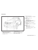
ENGINE COMPARTMENT SSI0388 VQ35HR ENGINE 1. 2. 3. 4. 5. Fuse/fusible link holder (P. 8-20) Battery (P. 8-13) Radiator filler cap (P. 8-6) Engine oil dipstick (P. 8-8) Engine oil filler cap (P. 8-8) 0-10 Illustrated table of contents 6. Brake fluid reservoir (P. 8-12) 7. Window washer fluid reservoir (P. 8-12) 8. Power steering fluid reservoir (P. 8-11) 9. Air cleaner (P. 8-16) 10. Drive belts (P. 8-15) 11. Coolant reservoir (P.
WARNING AND INDICATOR LIGHTS Warning light Name Page Warning light Name Page Indicator light Name Page All-Wheel Drive (AWD) warning light (AWD models)* 2-12 Intelligent Key system warning light 2-14 Automatic Transmission (AT) position indicator light 2-17 Anti-lock Braking System (ABS) warning light 2-12 Lane departure warning light (orange)* 2-14 Front fog light indicator light 2-18 Low tire pressure warning light 2-15 Front passenger air bag status light 2-18 Low washer fluid w
MEMO 0-12 Illustrated table of contents
1 Safety — Seats, seat belts and supplemental restraint system Seats . . . . . . . . . . . . . . . . . . . . . . . . . . . . . . . . . . . . . . . . . . . . .1-2 Front seats . . . . . . . . . . . . . . . . . . . . . . . . . . . . . . . . . . . . .1-2 Rear seats . . . . . . . . . . . . . . . . . . . . . . . . . . . . . . . . . . . . . .1-4 Head restraints . . . . . . . . . . . . . . . . . . . . . . . . . . . . . . . . .1-6 Front-seat active head restraint. . . . . . . . . . . . . . . . . . .
SEATS ● The seatback should not be reclined further than necessary for comfort. Seat belts are most effective when the passenger sits well back and straight up in the seat. If the seat back is reclined, the risk of sliding under the lap belt and being injured is increased. FRONT SEATS Front power seat adjustment Operating tips : SSS0133 WARNING ● Do not ride in a moving vehicle when the seatback is reclined. This can be dangerous. The shoulder belt will not be against your body.
SSS1052 SSS1051 Forward and backward : 1 forward or backward will Moving the switch 䊊 slide the seat forward or backward to the desired position. Reclining : 2 backward until the Move the recline switch 䊊 desired angle is obtained. To bring the seatback 2 forward. forward again, move the switch 䊊 The reclining feature allows adjustment of the seatback for occupants of different sizes for added comfort and to help obtain proper seat belt fit. (See “PRECAUTIONS ON SEAT BELT USAGE” later in this section.
● When operating the rear power seatback return, make sure that the vehicle is stopped and the transmission is in the P (Park) position. ● Make sure the lid of the rear seat cup holders is closed before folding the rear seatback. WARNING SSS1028 SSS0836 Type A Type B Lumbar support (if so equipped) : Type B The lumbar support feature provides lower back support to the driver. 1 up or down to adjust the Move the lever 䊊 seatback lumbar area.
SSS0828 Type A Power folding Luggage room switch (Type A) : 1 located on Push the front side of the switch 䊊 the right side or left side of the luggage room. The corresponding rear seatback will be folded down automatically. SSS0853 Type B SSS0829 Center console switch : Luggage room switch (Type B) : 1 located on Push the front side of the switch 䊊 the right side or left side of the luggage room. The corresponding rear seatback will be folded down automatically.
HEAD RESTRAINTS WARNING SSS0830 Manual folding Pull the lever 䊊 located on the right side or left side of the seatback before folding down the corresponding seatback. A Head restraints supplement the other vehicle safety systems. They may provide additional protection against injury in certain rear end collisions. Adjust the head restraints properly, as specified in this section. Check the adjustment after someone else uses the seat.
SSS0992 Components 1. 2. 3. 4. Head restraint Adjustment notches Lock knob Stalks SSS0997 Adjustment SSS0993 To raise the head restraint, pull it up. Adjust the head restraint so the center is level with the center of your ears.
SSS0994 To lower, push and hold the lock knob and push the head restraint down. SSS0995 Removal Use the following procedure to remove the adjustable head restraints. 1. Pull the head restraint up to the highest position. 2. Push and hold the lock knob. 3. Remove the head restraint from the seat. 4. Store the head restraint properly in a secure place so it is not loose in the vehicle. 5. Install and properly adjust the head restraint before an occupant uses the seating position.
Adjust the Active Head Restraints properly as described earlier in this section. ADJUSTABLE HEADREST WARNING SSS0508 FRONT-SEAT ACTIVE HEAD RESTRAINT The Active Head Restraint moves forward utilizing the force that the seatback receives from the occupant in a rear-end collision. The movement of the head restraint helps support the occupant’s head by reducing its backward movement and helping absorb some of the forces that may lead to whiplash-type injuries.
SSS0992 Components 1. 2. 3. 4. Adjustable headrest Adjustment notches Lock knob Stalks SSS0997 Adjustment Adjust the headrest so the center is level with the center of your ears. 1-10 Safety — Seats, seat belts and supplemental restraint system SSS0993 To raise the headrest, pull it up.
SSS0994 To lower, push and hold the lock knob and push the headrest down. SSS0995 Removal SSS0996 Install Use the following procedure to remove the adjustable headrests. 1. Pull the headrest up to the highest position. 2. Push and hold the lock knob. 3. Remove the headrest from the seat. 4. Store the headrest properly in a secure place so it is not loose in the vehicle. 5. Install and properly adjust the headrest before an occupant uses the seating position. 1.
SEAT BELTS PRECAUTIONS ON SEAT BELT USAGE If you are wearing your seat belt properly adjusted, and you are sitting upright and well back in your seat with both feet on the floor, your chances of being injured or killed in an accident and/or the severity of injury may be greatly reduced. INFINITI strongly encourages you and all of your passengers to buckle up every time you drive, even if your seating position includes a supplemental air bag. SSS0837 Most U.S.
WARNING ● Every person who drives or rides in this vehicle should use a seat belt at all times. Children should be properly restrained in the rear seat and, if appropriate, in a child restraint. ● The seat belt should be properly adjusted to a snug fit. Failure to do so may reduce the effectiveness of the entire restraint system and increase the chance or severity of injury in an accident. Serious injury or death can occur if the seat belt is not worn properly.
● Do not allow more than one person to use the same seat belt. ● Never carry more people in the vehicle than there are seat belts. ● If the seat belt warning light glows continuously while the ignition is turned ON with all doors closed and all seat belts fastened, it may indicate a malfunction in the system. Have the system checked by an INFINITI retailer. ● No changes should be made to the seat belt system.
PREGNANT WOMEN INFINITI recommends that pregnant women use seat belts. The seat belt should be worn snug, and always position the lap belt as low as possible around the hips, not the waist, and place the shoulder belt over your shoulder and across your chest. Never run the lap/shoulder belt over your abdominal area. Contact your doctor for specific recommendations. INJURED PERSONS INFINITI recommends that injured persons use seat belts, depending on the injury.
of movement in the seat. The ELR locks the seat belt when the vehicle slows down rapidly or during impacts. The Automatic Locking Retractor (ALR) mode (child restraint mode) locks the seat belt for child restraint installation. SSS0290 3. Position the lap belt portion low and snug on the hips as shown. 4. Pull the shoulder belt portion toward the retractor to take up extra slack. Be sure the shoulder belt is routed over your shoulder and across your chest.
● Grasp the shoulder belt and pull forward quickly. The retractor should lock and restrict further belt movement. WARNING ● After adjustment, release the adjustment button and try to move the shoulder belt anchor up and down to make sure it is securely fixed in position. If the retractor does not lock during this check or if you have any question about seat belt operation, see an INFINITI retailer. ● The shoulder belt anchor height should be adjusted to the position best for you.
seating position. See an INFINITI retailer for assistance with purchasing an extender if an extender is required. WARNING ● Only INFINITI seat belt extenders, made by the same company which made the original equipment seat belts, should be used with the INFINITI seat belts. SSS0671 Rear center seat belt The center seat belt buckle is identified by the CENTER mark. The center seat belt tongue can be fastened only into the center seat belt buckle.
CHILD SAFETY Children need adults to help protect them. They need to be properly restrained. In addition to the general information in this manual, child safety information is available from many other sources, including doctors, teachers, government traffic safety offices, and community organizations. Every child is different, so be sure to learn the best way to transport your child.
CHILD RESTRAINTS LARGER CHILDREN Children who are too large for child restraints should be seated and restrained by the seat belts which are provided. The seat belt may not fit properly if the child is less than 4 ft 9 in (142.5 cm) tall and weighs between 40 lb (18 kg) and 80 lb (36 kg). A booster seat should be used to obtain proper seat belt fit. WARNING Never let a child stand or kneel on any seat and do not allow a child in the cargo areas while the vehicle is moving.
PRECAUTIONS ON CHILD RESTRAINTS WARNING ● Failure to follow the warnings and instructions for proper use and installation of child restraints could result in serious injury or death of a child or other passengers in a sudden stop or collision: – The child restraint must be used and installed properly. Always follow all of the child restraint manufacturer’s instructions for installation and use. – Infants and children should never be held on anyone’s lap.
LATCH lower anchor Several manufacturers offer child restraints for infants and small children of various sizes. When selecting any child restraint, keep the following points in mind: WARNING ● Choose only a restraint with a label certifying that it complies with Federal Motor Vehicle Safety Standard 213 or Canadian Motor Vehicle Safety Standard 213.
SSS0840 LATCH lower anchor location LATCH lower anchor point locations The LATCH anchors are located at the rear of the seat cushion near the seatback. A label is attached to the seatback to help you locate the LATCH anchors. SSS0643 LATCH webbing-mounted attachment Installing child restraint LATCH anchor attachments LATCH compatible child restraints include two rigid or webbing-mounted attachments that can be connected to two anchors located at certain seating positions in your vehicle.
● Do not allow cargo to contact the top tether strap when it is attached to the top tether anchor. Properly secure the cargo so it does not contact the top tether strap. Cargo that is not properly secured or cargo that contacts the top tether strap may damage the top tether strap during a collision. Your child could be seriously injured or killed in a collision if the child restraint top tether strap is damaged.
SSS0649 Rear-facing rigid-mounted — step 2 SSS0639 SSS0650 Rear-facing — step 3 Rear-facing — step 4 3. For child restraints that are equipped with webbing-mounted attachments, remove any additional slack from the anchor attachments. Press downward and rearward firmly in the center of the child restraint with your hand to compress the vehicle seat cushion and seatback while tightening the webbing of the anchor attachments. 4.
Not all child restraints fit in all types of vehicles. 5. Check to make sure the child restraint is properly secured prior to each use. If the child restraint is loose, repeat steps 1 through 4. SSS0100 SSS0100 REAR-FACING CHILD RESTRAINT INSTALLATION USING THE SEAT BELTS WARNING The three-point seat belt with Automatic Locking Retractor (ALR) must be used when installing a child restraint. Failure to use the ALR mode will result in the child restraint not being properly secured.
SSS0654 SSS0655 SSS0656 Rear-facing — step 2 Rear-facing — step 3 Rear-facing — step 4 2. Route the seat belt tongue through the child restraint and insert it into the buckle until you hear and feel the latch engage. Be sure to follow the child restraint manufacturer’s instructions for belt routing. 3. Pull the shoulder belt until the belt is fully extended. At this time, the seat belt retractor is in the Automatic Locking Retractor (ALR) mode (child restraint mode).
7. Check to make sure that the child restraint is properly secured prior to each use. If the seat belt is not locked, repeat steps 1 through 6. After the child restraint is removed and the seat belt fully retracted, the ALR mode (child restraint mode) is canceled. FORWARD-FACING CHILD RESTRAINT INSTALLATION USING LATCH SSS0657 SSS0658 Rear-facing — step 5 Rear-facing — step 6 5.
SSS0645 SSS0646 SSS0647 Forward-facing web-mounted — step 2 Forward-facing rigid-mounted — step 3 Forward-facing — step 4 2. Secure the child restraint anchor attachments to the LATCH lower anchors. Check to make sure the LATCH attachment is properly attached to the lower anchors. 3. The back of the child restraint should be secured against the vehicle seatback. 4. For child restraints that are equipped with webbing-mounted attachments, remove any additional slack from the anchor attachments.
7. Check to make sure the child restraint is properly secured prior to each use. If the child restraint is loose, repeat steps 1 through 6. FORWARD-FACING CHILD RESTRAINT INSTALLATION USING THE SEAT BELTS WARNING SSS0638 Forward-facing — step 6 6. After attaching the child restraint, test it before you place the child in it. Push it from side to side while holding the child restraint near the LATCH attachment path. The child restraint should not move more than 1 inch (25 mm), from side to side.
2. Position the child restraint on the seat. Always follow the child restraint manufacturer’s instructions. The back of the child restraint should be secured against the vehicle seatback. If necessary, adjust or remove the head restraint or headrest to obtain the correct child restraint fit. If the head restraint or headrest is removed, store it in a secure place. Be sure to reinstall the head restraint or headrest when the child restraint is removed.
SSS0652 SSS0653 SSS0641 Forward-facing — step 5 Forward-facing — step 6 Forward-facing — step 8 5. Allow the seat belt to retract. Pull up on the shoulder belt to remove any slack in the belt. 6. Remove any additional slack from the seat belt; press downward and rearward firmly in the center of the child restraint with your knee to compress the vehicle seat cushion and seatback while pulling up on the seat belt. 7.
9. Check to make sure the child restraint is properly secured prior to each use. If the seat belt is not locked, repeat steps 2 through 8. SSS0676 Forward-facing — step 10 10. If the child restraint is installed in the front passenger seat, place the ignition switch in the ON position. The front passenger air bag status light should illuminate. If this light is not illuminated, see “Front passenger air bag and status light” in this section. Move the child restraint to another seating position.
If necessary, raise or remove the headrest to position the top tether strap over the top of the seatback. If the headrest is removed, store it in a secure place. Be sure to reinstall the headrest when the child restraint is removed. See ⬙Adjustable headrest⬙ in this section for headrest adjustment, removal and installation information. 3. Refer to the appropriate child restraint installation procedure steps in this section before tightening the tether strap.
Booster seat installation CAUTION Do not use the lap/shoulder belt Automatic Locking Retractor (ALR) mode when using a booster seat with the seat belts. LRS0464 ● If the booster seat is compatible with your vehicle, place your child in the booster seat and check the various adjustments to be sure the booster seat is compatible with your child. Always follow all recommended procedures.
LRS0454 Front passenger position 3. The booster seat should be positioned on the vehicle seat so that it is stable. If necessary, adjust or remove the head restraint or headrest to obtain the correct booster seat fit. If the head restraint or headrest is removed, store it in a secure place. Be sure to reinstall the head restraint or headrest when the booster seat is removed.
SUPPLEMENTAL RESTRAINT SYSTEM PRECAUTIONS ON SUPPLEMENTAL RESTRAINT SYSTEM This Supplemental Restraint System (SRS) section contains important information concerning the following systems.
WARNING ● The front air bags ordinarily will not inflate in the event of a side impact, rear impact, rollover, or lower severity frontal collision. Always wear your seat belts to help reduce the risk or severity of injury in various kinds of accidents. ● The front passenger air bag will not inflate if the passenger air bag status light is lit or if the front passenger seat is unoccupied. See “Front passenger air bag and status light” later in this section.
● The driver and front passenger seat belt buckles are equipped with sensors that detect if the seat belts are fastened. The Advanced Air Bag System monitors the severity of a collision and seat belt usage then inflates the air bags as needed. Failure to properly wear seat belts can increase the risk or severity of injury in an accident. ● The front passenger seat is equipped with an occupant classification sensor (pattern sensor) that turns the front passenger air bag OFF under some conditions.
WARNING ● Never let children ride unrestrained or extend their hands or face out of the window. Do not attempt to hold them in your lap or arms. Some examples of dangerous riding positions are shown in the illustrations. SSS0099 ● Children may be severely injured or killed when the front air bags, side air bags or curtain air bags inflate if they are not properly restrained. Pre-teens and children should be properly restrained in the rear seat, if possible.
SSS0140 SSS0159 WARNING Front seat-mounted side-impact supplemental air bags and roof-mounted curtain side-impact supplemental air bags: ● The side air bags and curtain air bags ordinarily will not inflate in the event of a frontal impact, rear impact, rollover or lower severity side collision. Always wear your seat belts to help reduce the risk or severity of injury in various kinds of accidents.
7. Roof-mounted curtain side-impact supplemental air bag inflators 8. Air bag Control Unit (ACU) 9. Satellite sensors 10. Seat belt pretensioner INFINITI ADVANCED AIR BAG SYSTEM (front seats) This vehicle is equipped with the INFINITI Advanced Air Bag System for the driver and front passenger seats. This system is designed to meet certification requirements under U.S. regulations. It is also permitted in Canada.
information from the crash zone sensor, the Air bag Control Unit (ACU), the diagnosis sensor unit, seat belt buckle sensors and the occupant classification sensor (pattern sensor). Inflator operation is based on the severity of a collision and seat belt usage for the driver. For the front passenger, the occupant classification sensor is also monitored.
Status light : The front passenger air bag status light is located under the climate controls. After the ignition switch is placed in the ON position, the front passenger air bag status light illuminates for about 7 seconds and then turns off or illuminates depending on the front passenger occupied status. The light operates as follows: is ● Unoccupied passenger seat: The OFF and the front passenger air bag is OFF and will not inflate in a crash.
INFINITI recommends that pre-teens and children be properly restrained in a rear seat. INFINITI also recommends that appropriate child restraints and booster seats be properly installed in a rear seat. If this is not possible, the occupant classification sensor is designed to operate as described above to turn the front passenger air bag OFF for specified child restraints.
● Do not place objects with sharp edges on the seat. Also, do not place heavy objects on the seat that will leave permanent impressions in the seat. Such objects can damage the seat or occupant classification sensor (pattern sensor). This can affect the operation of the air bag system and result in serious personal injury. ● Tampering with the air bag system may result in serious personal injury.
forces in another type of collision are similar to those of a higher severity side impact. They are designed to inflate on the side where the vehicle is impacted. They may not inflate in certain side collisions on the side where the vehicle is impacted. Vehicle damage (or lack of it) is not always an indication of proper side air bag and curtain air bag operation.
WARNING ● Do not place any objects near the seatback of the front seats. Also, do not place any objects (an umbrella, bag, etc.) between the front door finisher and the front seat. Such objects may become dangerous projectiles and cause injury if a side air bag inflates. ● Right after inflation, several front seatmounted side air bags and roof-mounted curtain air bag system components will be hot. Do not touch them; you may severely burn yourself.
becomes involved in certain types of collisions, helping to restrain front seat occupants. The pretensioner is encased with the seat belt retractor. These seat belts are used the same way as conventional seat belts. When a pretensioner activates, smoke is released and a loud noise may be heard. The smoke is not harmful, and it does not indicate a fire. Care should be taken not to inhale it as it may cause irritation and choking. Those with a history of a breathing condition should get fresh air promptly.
When the ignition switch is in the ON position, the supplemental air bag warning light illuminates for about 7 seconds and then turns off. This means the system is operational. If any of the following conditions occur, the front air bag, side air bag, curtain air bag and pretensioner systems need servicing: ● The supplemental air bag warning light remains on approximately 7 seconds after the ignition switch is pushed to the ON position. ● The supplemental air bag warning light flashes intermittently.
MEMO Safety — Seats, seat belts and supplemental restraint system 1-51
2 Instruments and controls Cockpit. . . . . . . . . . . . . . . . . . . . . . . . . . . . . . . . . . . . . . . . . . . 2-2 Instrument panel . . . . . . . . . . . . . . . . . . . . . . . . . . . . . . . . . . 2-4 Meters and gauges . . . . . . . . . . . . . . . . . . . . . . . . . . . . . . . . 2-5 Speedometer and odometer . . . . . . . . . . . . . . . . . . . . . 2-6 Tachometer . . . . . . . . . . . . . . . . . . . . . . . . . . . . . . . . . . . . 2-7 Engine coolant temperature gauge . . . . . . . . . . .
Card holder . . . . . . . . . . . . . . . . . . . . . . . . . . . . . . . . . . . 2-47 Seat-mounted jacket hanger (if so equipped) . . . . . . . . . . . . . . . . . . . . . . . . . . . . . . . . . . . . 2-47 Coat hooks . . . . . . . . . . . . . . . . . . . . . . . . . . . . . . . . . . . 2-48 Luggage hooks. . . . . . . . . . . . . . . . . . . . . . . . . . . . . . . . 2-48 Cargo cover (if so equipped) . . . . . . . . . . . . . . . . . . . 2-48 Roof rack (if so equipped). . . . . . . . . . . . . . . . . . .
COCKPIT SSI0623 1. TRIP/RESET switch for twin trip odometer (P. 2-6) 2. Instrument brightness control switch (P. 2-38) 3. Headlight, fog light and turn signal switch (P. 2-34) 2-2 Instruments and controls 4. Trip computer switch (P. 2-27) 5. Windshield wiper and washer switch (P. 2-32) 6. Warning systems switch (if so equipped) — Forward Collision Warning (FCW) (P. 5-66) — Lane Departure Warning (LDW) (P. 5-17) — Blind Spot Warning (BSW) (P. 5-25) 7. Hood release handle (P. 3-16) 8.
15. Steering-wheel-mounted controls (right side) — Cruise control switches (P. 5-32) — Intelligent Cruise Control (ICC) switches (if so equipped) (P. 5-34) — Lane Departure Prevention (LDP) switch (if so equipped) (P. 5-17) — Distance Control Assist (DCA) switch (if so equipped) (P. 5-54) 16. Center-console-mounted controls — Heated seat switches (if so equipped) (P. 2-40) — Rear seat power return switches (if so equipped) (P. 1-4) — SNOW mode switch (P.
INSTRUMENT PANEL — Bluetooth姞 Hands-Free Phone System (if so equipped) (without navigation system) (P. 4-103) — Around View Monitor (if so equipped) (P. 4-27) — Rearview monitor (if so equipped) (P. 4-22) 8. Front passenger supplemental air bag (P. 1-37) 9. Fuse box cover (P. 8-20) 10. Parking brake (P. 5-16) 11. Push-button ignition switch (P. 5-8) 12. Front passenger air bag status light (P. 1-42) 13. Power outlet (P. 2-44) 14. Rear window defogger switch (P. 2-34) 15. Automatic climate control system (P.
METERS AND GAUGES *: The needle indicators in the speedometer, tachometer, engine coolant temperature gauge and fuel gauge may move slightly after the ignition switch is pushed to the OFF position. This is not a malfunction. SIC4694 1. 2. 3. 4. Tachometer (P. 2-7) Warning/Indicator lights (P. 2-11) Speedometer (P. 2-6) Engine coolant temperature gauge (P. 2-7) 5. Dot matrix liquid display/Odometer/twin trip (P. 2-20) 6. Fuel gauge (P.
Changing the display : 3 at the Pushing the TRIP A/B RESET switch 䊊 bottom left of the combination meter panel changes the display as follows: TRIP A → TRIP B → TRIP A Resetting the trip odometer : 3 for more Pushing the TRIP A/B RESET switch 䊊 than 1 second resets the trip odometer to zero. SIC4695 Speedometer SPEEDOMETER AND ODOMETER Speedometer The speedometer indicates vehicle speed in miles per hour (MPH) and kilometers per hour (km/h).
CAUTION If the gauge indicates engine coolant temperature near the hot (H) end of the normal range, reduce vehicle speed to decrease temperature. If gauge is over the normal range, stop the vehicle as soon as safely possible. If the engine is overheated, continued operation of the vehicle may seriously damage the engine. See “IF YOUR VEHICLE OVERHEATS” in the “6. In case of emergency” section for immediate action required.
COMPASS (if so equipped) There will be a small reserve of fuel in the tank when the fuel gauge needle reaches “E”. indicates that the fuel-filler door is The located on the passenger’s side of the vehicle. CAUTION SIC4698 FUEL GAUGE The gauge indicates the approximate fuel level in the tank. ● If the vehicle runs out of fuel, the malfunction indicator light (MIL) may come on. Refuel as soon as possible. After a few light should turn off.
brate the compass by driving your vehicle on your everyday route. The compass will be calibrated once it has tracked 3 complete circles. To turn on and off the compass manually, push A while the ignition switch is switch 䊊 the in the ON position.
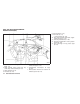
ZONE VARIATION CHANGE PROCEDURE The difference between magnetic north and geographical north is known as variance. In some areas, this difference can sometimes be great enough to cause false compass readings. Follow these instructions to set the variance for your particular location if this happens: 1. Push the switch for more than 3 seconds. The current zone number will appear in the display. 2. Find your current location and variance number on the zone map. NOTE: Use zone number 5 for Hawaii. 3.
WARNING/INDICATOR LIGHTS AND AUDIBLE REMINDERS All-Wheel Drive (AWD) warning light (AWD models)* Intelligent Key warning light Front fog light indicator light Anti-lock Braking System (ABS) warning light Lane departure warning light (orange)* Front passenger air bag status light Low tire pressure warning light High beam indicator light Automatic transmission check warning light Low washer fluid warning light Intelligent Brake Assist (IBA) off indicator light* Brake warning light Master warning l
CHECKING BULBS With all doors closed, apply the parking brake and push the ignition switch to the ON position without starting the engine. The following lights will come on (if so equipped): , , or , , , , The following lights come on briefly and then go off (if so equipped): , or , , , , , , , WARNING LIGHTS All-Wheel Drive (AWD) warning light (AWD models) The warning light comes on when the ignition switch is pushed to ON. It turns off soon after the engine is started.
Automatic transmission check warning light When the ignition switch is pushed to the ON position, the light comes on for 2 seconds. If the light comes on at any other time, it may indicate the transmission is not functioning properly. Have your INFINITI retailer check and repair the transmission. or Brake warning light This light functions for both the parking brake and the foot brake systems. 2. If the brake fluid level is correct, have the warning system checked by an INFINITI retailer.
CAUTION Do not continue driving if the alternator belt is loose, broken or missing. Distance Control Assist (DCA) system warning light (orange; if so equipped) This light comes on if there is a malfunction in the Distance Control Assist (DCA) system. If the warning light illuminates, park the vehicle in a safe place. Turn the engine off, restart the engine, resume driving and turn on the DCA system again.
If the light comes on in orange and remains on, it may indicate that the LDW and LDP systems are not functioning properly. Have the systems checked by an INFINITI retailer. See “LANE DEPARTURE WARNING (LDW) SYSTEM/LANE DEPARTURE PREVENTION (LDP) SYSTEM” in the “5. Starting and driving” section. Low tire pressure warning light Your vehicle is equipped with a Tire Pressure Monitoring System (TPMS) that monitors the tire pressure of all tires except the spare.
● When a spare tire is mounted or a wheel is replaced, the TPMS will not function and the low tire pressure warning light will flash for approximately 1 minute. The light will remain on after 1 minute. Contact your INFINITI retailer as soon as possible for tire replacement and/or system resetting. ● Replacing tires with those not originally specified by INFINITI could affect the proper operation of the TPMS. (See “WINDOW WASHER FLUID” in the “8. Maintenance and do-it-yourself” section.
light will illuminate. The supplemental air bag warning light will turn off after about 7 seconds if the supplemental front air bag and supplemental side air bag, curtain side-impact air bag systems and/or pretensioner seat belt are operational. If any of the following conditions occur, the front air bag, side air bag, curtain air bag and pretensioner systems needs servicing and your vehicle must be taken to your nearest INFINITI retailer.
Front fog light indicator light The front fog light indicator light illuminates when the front fog lights are on. (See “FOG LIGHT SWITCH” later in this section.) Front passenger air bag status light The front passenger air bag status light ( ) will be lit and the passenger front air bag will be OFF depending on how the front passenger seat is being used. For front passenger air bag status light operation, see “INFINITI ADVANCED AIR BAG SYSTEM (front seats)” in the “1.
closed tightly, and that the vehicle has at least 3 US gallons (14 liters) of fuel in the fuel tank. light should After a few driving trips, the turn off if no other potential emission control system malfunction exists. If this indicator light remains on for 20 seconds and then blinks for 10 seconds when the engine is not running, it indicates that the vehicle is not ready for an emission control system inspection/maintenance test. (See “READINESS FOR INSPECTION/MAINTENANCE (I/M) TEST” in the “9.
DOT MATRIX LIQUID CRYSTAL DISPLAY AUDIBLE REMINDERS Key reminder chime A chime will sound if the driver side door is opened while the ignition switch is pushed to the ACC position or pushed to the OFF or LOCK position with the Intelligent Key left in the Intelligent Key port. Make sure the ignition switch is pushed to the OFF position, and take the Intelligent Key with you when leaving the vehicle.
For detailed information about each system, see the following sections: ● Automatic Transmission (AT) – “WARNING/INDICATOR LIGHTS AND AUDIBLE REMINDERS” earlier in this section. – “DRIVING THE VEHICLE” in the “5. Starting and driving” section. ● Intelligent Cruise Control (ICC) system – “INTELLIGENT CRUISE CONTROL (ICC) SYSTEM (FULL SPEED RANGE)” in the “5. Starting and driving” section. ● Distance Control Assist (DCA) system – “DISTANCE CONTROL ASSIST (DCA) SYSTEM” in the “5.
SIC4686 2-22 Instruments and controls
INDICATORS FOR OPERATION 1. Engine start operation indicator This indicator appears when the selector lever is in the P (Park) position. This indicator means that the engine will start by pushing the ignition switch with the brake pedal depressed. 2. Steering lock release malfunction indicator (if so equipped) This indicator appears when the steering wheel cannot be released from the LOCK position.
SHIFT “P” warning → (Move the selector lever to “P”) → PUSH warning → (Push the ignition switch → ignition switch position is turned to ON) → PUSH warning → (Push the ignition switch → ignition switch position is turned to OFF) 8. Intelligent Key battery discharge indicator This indicator appears when the Intelligent Key battery is running out of power. If this indicator appears, replace the battery with a new one. (See “INTELLIGENT KEY BATTERY REPLACEMENT” in the “8.
Cruise set switch indicator : The indicator is displayed while the vehicle speed is controlled by the cruise control system. If the indicator blinks while the engine is running, it may indicate that the cruise control system is not functioning properly. Have the system checked by an INFINITI retailer. See “CRUISE CONTROL” in the “5. Starting and driving” section for details. 18. Intelligent Cruise Control (ICC) system MAIN switch indicator (if so equipped) 19.
INDICATORS FOR MAINTENANCE 1. Engine oil replacement indicator This indicator appears when the set time comes for changing the engine oil. You can set or reset the distance for changing the engine oil. (See “TRIP COMPUTER” later in this section.) 2. Oil filter replacement indicator This indicator appears when the set time comes for replacing the oil filter. You can set or reset the distance for replacing the oil filter. (See “TRIP COMPUTER” later in this section.) 3.
Each time the A is pushed, the switch 䊊 display will change as follows: Current fuel consumption → Average fuel consumption and speed → Elapsed time and trip odometer → Distance to empty (dte) → Outside air temperature (ICY) → Setting → Warning check 1. Current fuel consumption SIC3625 TRIP COMPUTER Switches for the trip computer are located on the right side of the combination meter panel. To operate the trip computer, push the side or front of the switches as shown above. A 䊊 B 䊊 switch 2.
4. Distance to empty (dte — mls or km) The distance to empty (dte) mode provides you with an estimation of the distance that can be driven before refueling. The dte is constantly being calculated, based on the amount of fuel in the fuel tank and the actual fuel consumption. The display is updated every 30 seconds. The outside air temperature mode includes a low temperature warning feature. If the outside air temperature is below 37°F (3°C), the warning is displayed on the screen.
SECURITY SYSTEMS ● TIRE 7. Warning check Select this submenu to set or reset the distance for replacing tires. ● OTHER Select this submenu and set or reset the distance for replacing items other than the engine oil, oil filter and tires. The maintenance distance will increase by 250 miles (500 km) up to 18,500 miles (30,000 km). To increase the number by 500 miles (1,000 km), push and hold the button. SKIP : A to move to the switch 䊊 Push the warning check mode. Push the menus.
The system helps deter vehicle theft but cannot prevent it, nor can it prevent the theft of interior or exterior vehicle components in all situations. Always secure your vehicle even if parking for a brief period. Never leave your Intelligent Key(s) in the vehicle, and always lock it when unattended. Be aware of your surroundings, and park in secure, well-lit areas whenever possible.
The alarm is activated by: ● Unlocking the door or opening the lift gate without using the button on the Intelligent Key, the door handle request switch or the mechanical key. (Even if the door is opened by releasing the door inside lock knob, the alarm will activate.) ● Opening the hood.
WINDSHIELD WIPER AND WASHER SWITCH If the light still remains on and/or the engine will not start, see an INFINITI retailer for INFINITI Vehicle Immobilizer System service as soon as possible. Please bring all Intelligent Keys that you have when visiting an INFINITI retailer for service. WARNING In freezing temperatures the washer solution may freeze on the window and obscure your vision which may lead to an accident. Warm the window with the defroster before you wash the window.
“HOW TO USE SETTING BUTTON” in the “4. Monitor, climate, audio, phone and voice recognition systems” section. 2 Low — continuous low speed operation 䊊 3 High — continuous high speed operation 䊊 4 to have one sweep Push the lever up 䊊 operation of the wiper. 5 to operate the Pull the lever toward you 䊊 washer. Then the wiper will also operate several times. SIC3626 WINDSHIELD WIPER AND WASHER OPERATION The windshield wiper and washer operates when the ignition switch is in the ON position.
REAR WINDOW AND OUTSIDE MIRROR DEFROSTER SWITCH 2 Low (ON) — continuous low speed operation 䊊 XENON HEADLIGHTS (if so equipped) 3 to operate the Push the switch forward 䊊 washer. Then the wiper will also operate several times. WARNING HIGH VOLTAGE Wiper drip wipe system (if so equipped): ● When xenon headlights are on, they produce a high voltage. To prevent an electric shock, never attempt to modify or disassemble. Always have your xenon headlights replaced at an INFINITI retailer.
● The life of xenon headlights will be shortened by frequent on-off operation. It is generally desirable not to turn off the headlights for short intervals (for example, when the vehicle stops at a traffic signal). Even when the daytime running lights are active (Canada only), the xenon headlights do not turn on. This way the life of the xenon headlights is not reduced.
If the ignition switch is pushed to the OFF position and one of the doors is opened and this condition is continued, the headlights remain on for 5 minutes. Automatic headlights off delay : You can keep the headlights on for up to 180 seconds after you push the ignition switch to OFF and open any door then close all the doors. You can adjust the period of the automatic headlights off delay from 0 seconds (OFF) to 180 seconds. The factory default setting is 45 seconds.
position and the ignition switch in the ACC, OFF or LOCK position. Daytime running light system (Canada only) or When the headlight switch is in the position while the ignition switch is in the ON position, the lights will automatically turn off 5 minutes after the ignition switch has been pushed to the OFF position. The daytime running lights automatically illuminate when the engine is started with the parking brake released.
The dot matrix liquid crystal display returns to the normal display under the following conditions: ● when the instrument brightness control switch is not operated for more than 5 seconds. or switch on the right ● when the side of the combination meter panel is pushed. SIC3628 Instrument brightness control The instrument brightness control switch can be operated when the ignition switch is in the ON position.
HAZARD WARNING FLASHER SWITCH SIC3271 TURN SIGNAL SWITCH 1 Turn signal 䊊 Move the lever up or down to signal the turning direction. When the turn is completed, the turn signals cancel automatically. 2 Lane change signal 䊊 To indicate a lane change, move the lever up or down to the point where lights begin flashing. SIC3272 FOG LIGHT SWITCH To turn the fog lights on, turn the headlight position, then turn the switch to the position. To turn them off, switch to the turn the switch to the OFF position.
HORN HEATED SEATS (if so equipped) The flasher can be actuated with the ignition switch in any position. WARNING Do not use or allow occupants to use the seat heater if you or the occupants cannot monitor elevated seat temperatures or have an inability to feel pain in body parts that contact the seat. Use of the seat heater by such people could result in serious injury. Some state laws may prohibit the use of the hazard warning flasher switch while driving.
The heater is controlled by a thermostat, automatically turning the heater on and off. The indicator light will remain on as long as the switch is on. ● If any malfunctions are found or the heated seat does not operate, turn the switch off and have the system checked by an INFINITI retailer. When the vehicle’s interior is warmed, or before you leave the vehicle, be sure to turn off the switch. SSS0911 The front seats are warmed by built-in heaters.
WARNING SYSTEMS SWITCH (if so equipped) The BSW system will illuminate the Blind Spot Warning (BSW) indicator lights, located next to the outside mirrors, when the radar sensors detect a vehicle in the detection zone. If the turn signal is activated in the direction of the detected vehicle, a chime sounds twice and the BSW indicator light will flash. (See “BLIND SPOT WARNING (BSW) SYSTEM” in the “5. Starting and driving” section.
SNOW MODE SWITCH INTELLIGENT BRAKE ASSIST (IBA) OFF SWITCH (if so equipped) VEHICLE DYNAMIC CONTROL (VDC) OFF SWITCH SIC3602 SIC3844 JVS0033X For driving or starting the vehicle on snowy roads or slippery areas, turn on the SNOW 1 on the mode switch. The indicator light 䊊 switch will illuminate. When the SNOW mode is activated, engine output is controlled to avoid wheel spin. The vehicle should be driven with the Intelligent Brake Assist (IBA) system on for most driving conditions.
CLOCK POWER OUTLET The power outlet is used for powering electrical accessories such as cellular telephones. CAUTION ● The outlet and plug may be hot during or immediately after use. ● Do not use with accessories that exceed a 12 volt, 120W (10A) power draw. Do not use double adapters or more than one electrical accessory. SIC3867 SIC3325 ● Avoid using power outlet when the air conditioner, headlights or rear window defroster is on.
STORAGE 2 . To hold a taller container, push the button 䊊 The upper bottom will be folded up. CUP HOLDERS CAUTION ● Avoid abrupt starting and braking when the cup holder is being used to prevent spilling the drink. If the liquid is hot, it can scald you or your passenger. ● Use only soft cups in the cup holder. Hard objects can injure you in an accident. SIC3632 Front 1 . To open the cup holder, push the knob 䊊 A will be folded down when inserting The flap 䊊 a large container.
SIC3633 Rear The cup holders for rear passengers are located on the rear center armrest. To open the cup holder, pull the lid. Make sure that the lid is closed before storing the rear center armrest in the seatback. SIC3246 SUNGLASSES HOLDER WARNING Keep the sunglasses holder closed while driving to prevent an accident. 1 . To open the sunglasses holder, push 䊊 CAUTION ● Do not use for anything other than glasses. ● Do not leave glasses in the sunglasses holder while parking in direct sunlight.
SIC4687 CONSOLE BOX To open the console box, push the button SIC3663 CARD HOLDER 䊊. 1 To close, push the lid down until latched. The inner tray (if so equipped) can be posi2 . Make sure that tioned to the front or rear 䊊 the arrow mark on the tray points toward the A are aligned in the slits. front and the bosses 䊊 Pull the sun visor down A .
SIC3248 COAT HOOKS SIC4072 LUGGAGE HOOKS The coat hooks are equipped beside the rear personal lights. CAUTION Do not place items which are more than 2 lb (1 kg) on the hook. WARNING ● Always make sure that the cargo is properly secured. Use the suitable ropes and hooks. ● Unsecured cargo can become dangerous in an accident or sudden stop. CAUTION Do not apply a total load of more than 22 lb (10 kg) to a single hook.
● If the cargo cover contacts the top tether strap when it is attached to the top tether anchor, remove the cargo cover from the vehicle or secure it on the cargo floor below its attachment location. If the cargo cover is not removed, it may damage the top tether strap during a collision. Your child could be seriously injured or killed in a collision if the child restraint top tether strap is damaged. SIC3637 SIC3638 To stow the cargo cover, remove it from the hooks and hold until it is retracted.
WINDOWS ING INFORMATION” in the “9. Technical and consumer information” section. WARNING ● Drive extra carefully when the vehicle is loaded at or near the cargo carrying capacity, especially if the significant portion of that load is carried on the roof rack. SIC3639 ROOF RACK (if so equipped) Always distribute the luggage evenly on the roof rack. Do not load more than 220 lb (100 kg) on the roof rails.
SIC3640 Main power window switch (driver’s side) 1. 2. 3. 4. 5. Driver side window Front passenger side window Rear left passenger side window Rear right passenger side window Window lock button A or To open or close the window, push down 䊊 B the switch and hold it. The main pull up 䊊 switch (driver side switches) will open or close all the windows. Locking passengers’ windows SIC3241 Passenger side power window switch The passenger side switch will open or close only the corresponding window.
MOONROOF (if so equipped) Auto reverse function WARNING There are some small distances immediately before the closed position which cannot be detected. Make sure that all passengers have their hands, etc., inside the vehicle before closing the window. If the control unit detects something caught in the window as it is closing, the window will be immediately lowered.
To stop the roof, push the switch once more while it is opening or closing. Auto reverse function WARNING There are some small distances immediately before the closed position which cannot be detected. Make sure that all passengers have their hands, etc., inside the vehicle before closing the moonroof. SIC3243 Sunshade The sunshade will open automatically when the moonroof is opened. However, it must be closed manually.
WELCOME LIGHT INTERIOR LIGHTS mination will illuminate when you approach the vehicle with the Intelligent Key (within approximately 3.3 feet (1 m) of the antenna built inside the door handles) and the following conditions are met. ● All doors are closed and locked. ● The ignition switch is in the LOCK or OFF position. ● The Intelligent Key is outside the vehicle. ● The puddle light operates within a set duration.
DOOR position 2 , the When the switch is in the DOOR position 䊊 map lights and rear personal lights will illuminate under the following conditions: ● ignition switch is switched to the LOCK position – remain on for about 15 seconds. SIC3250 PERSONAL LIGHTS Rear Push the button as illustrated to turn the light on or off. SIC3251 INTERIOR LIGHT CONTROL SWITCH The interior light control switch has three positions: ON, DOOR and OFF.
VANITY MIRROR LIGHTS CARGO LIGHT (if so equipped) When the auto interior illumination is set to the OFF position (see “VEHICLE INFORMATION AND SETTINGS” in the “4. Monitor, climate, audio, phone and voice recognition systems” section), the lights will illuminate under the following condition: ● any door is opened with the ignition switch in any position – remain on while the door is opened. When the door is closed, the lights go off.
HOMELINK姞 UNIVERSAL TRANSCEIVER (if so equipped) HomeLink姞 Universal Transceiver provides a convenient way to consolidate the functions of up to three individual hand-held transmitters into one built-in device. HomeLink姞 Universal Transceiver: ● Will operate most Radio Frequency (RF) devices such as garage doors, gates, home and office lighting, entry door locks and security systems. ● Is powered by your vehicle’s battery. No separate batteries are required.
SIC3182 SIC3183 1. To begin, push and hold the 2 outer HomeLink姞 buttons (to clear the memory) A blinks (after 20 until the indicator light 䊊 seconds). Release both buttons. 2. Position the end of the hand-held transmitter 1-3 inches away from the HomeLink姞 surface. 3. Using both hands, simultaneously push and hold both the HomeLink姞 button you want to program and the hand-held transmitter button. DO NOT release the buttons until step 4 has been completed. 2-58 Instruments and controls 4.
NOTE: Once you have pushed and released the training button on the garage door opener’s motor and the “training light” is lit, you have 30 seconds in which to perform step 7. For convenience, use the help of a second person to assist when performing this step. 7. Quickly (within 30 seconds of pushing and releasing the garage door opener training button) and firmly push and release the HomeLink姞 button you’ve just programmed. Push and release the HomeLink姞 button up to three times to complete the training.
CLEARING THE PROGRAMMED INFORMATION Individual buttons cannot be cleared, however to clear all programming, push and hold the two outside buttons and release when the indicator light begins to flash (in approximately 20 seconds). REPROGRAMMING A SINGLE HOMELINK姞 BUTTON To reprogram a HomeLink姞 Universal Transceiver button, complete the following. 1. Push and hold the desired HomeLink姞 button. Do not release the button until step 4 has been completed. 2.
3 Pre-driving checks and adjustments Keys . . . . . . . . . . . . . . . . . . . . . . . . . . . . . . . . . . . . . . . . . . . . . 3-2 Intelligent Key . . . . . . . . . . . . . . . . . . . . . . . . . . . . . . . . . 3-2 Valet hand-off. . . . . . . . . . . . . . . . . . . . . . . . . . . . . . . . . . 3-3 Doors . . . . . . . . . . . . . . . . . . . . . . . . . . . . . . . . . . . . . . . . . . . . 3-4 Locking with mechanical key . . . . . . . . . . . . . . . . . . . .
KEYS A key number plate is supplied with your keys. Record the key number and keep it in a safe place (such as your wallet), not in the vehicle. If you lose your keys, see an INFINITI retailer for duplicates by using the key number. INFINITI does not record any key numbers so it is very important to keep track of your key number plate. all memory in the Intelligent Key components when registering new keys, be sure to take all Intelligent Keys that you have to the INFINITI retailer.
CAUTION – Do not allow the Intelligent Key to come into contact with water or salt water, and do not wash it in a washing machine. This could affect the system function. Always carry the mechanical key installed in the Intelligent Key. ● If an Intelligent Key is lost or stolen, INFINITI recommends erasing the ID code of that Intelligent Key. This will prevent the Intelligent Key from unauthorized use to unlock the vehicle.
DOORS SETTING BUTTON” in the “4. Monitor, climate, audio, phone and voice recognition systems” section.) WARNING ● Always have the doors locked while driving. Along with the use of seat belts, this provides greater safety in the event of an accident by helping to prevent persons from being thrown from the vehicle. This also helps keep children and others from unintentionally opening the doors, and will help keep out intruders.
Lockout protection When the power door lock switch (driver or front passenger) is moved to the lock position with the Intelligent Key in the port and any door open, all doors will lock and unlock automatically. With the Intelligent Key left in the vehicle (not in the Intelligent Key port) and any door open, all doors will unlock automatically and a chime will sound after the door is closed. SPA1814 LOCKING WITH INSIDE LOCK KNOB To lock the door individually, move the inside 1 .
INTELLIGENT KEY SYSTEM 3. Within 20 seconds of performing Step 2, push and hold the power door lock switch position (UNLOCK) for more to the than 5 seconds. 4. When activated, the hazard indicator will flash twice. When deactivated, the hazard indicator will flash once. 5. The ignition switch must be placed in the OFF and ON position again between each setting change. When the automatic door unlock system is deactivated, the doors do not unlock when the ignition switch is placed in the OFF position.
● Never leave the Intelligent Key in the vehicle when you leave the vehicle. In such cases, correct the operating conditions before using the Intelligent Key function or use the mechanical key. The Intelligent Key is always communicating with the vehicle as it receives radio waves. The Intelligent Key system transmits weak radio waves. Environmental conditions may interfere with the operation of the Intelligent Key system under the following operating conditions.
If an Intelligent Key is lost or stolen, INFINITI recommends erasing the ID code of that Intelligent Key from the vehicle. This may prevent the unauthorized use of the Intelligent Key to operate the vehicle. For information regarding the erasing procedure, contact an INFINITI retailer. SPA2074 INTELLIGENT KEY OPERATING RANGE The Intelligent Key functions can only be used when the Intelligent Key is within the specified 1 .
● Do not pull the door handle before pushing the door handle request switch. The door will be unlocked but will not open. Release the door handle once and pull it again to open the door. ● The Intelligent Key system (opening/closing doors with the door handle request switch) can be set to remain inactive. (See “VEHICLE INFORMATION AND SETTINGS” in the “4. Monitor, climate, audio, phone and voice recognition systems” section.
When you carry the Intelligent Key with you, you can lock or unlock all doors by pushing the door handle request switch (driver’s or front passenA or the lift gate request switch 䊊 B ger’s) 䊊 within the range of operation. When you lock or unlock the doors or the lift gate, the hazard indicator will flash and the horn (or the outside chime) will sound as a confirmation. For details, see “Setting hazard indicator and horn mode” later in this section. Locking doors and fuel-filler door SPA2467 1.
BATTERY SAVER SYSTEM WARNING SIGNALS When all the following conditions are met for 60 minutes, the battery saver system will cut off the power supply to prevent battery discharge. To help prevent the vehicle from moving unexpectedly by erroneous operation of the Intelligent Key listed on the following chart or to help prevent the vehicle from being stolen, chime or beep sounds inside and outside the vehicle and a warning displays in the dot matrix liquid crystal display.
TROUBLESHOOTING GUIDE Symptom Possible cause When pushing the ignition switch to stop the engine The SHIFT P warning appears on the The selector lever is not in the P display and the inside warning chime (Park) position. sounds continuously. When opening the driver’s door to get out of the vehicle The inside warning chime sounds continuously.
REMOTE KEYLESS ENTRY SYSTEM WARNING The Intelligent Key transmits radio waves when the buttons are pushed. The FAA advises that the radio waves may affect aircraft navigation and communication systems. Do not operate the Intelligent Key while on an airplane. Make sure that the buttons are not operated unintentionally when the unit is stored for a flight.
4. All the doors, the lift gate and fuel-filler door will lock. 5. The hazard indicator flashes twice and the horn chirps once. *1: Doors will lock with the Intelligent Key while the ignition switch is in the ACC or ON position. *2: Doors will not lock with the Intelligent Key while any door is open. Unlocking doors and fuel-filler door 2 on the 1. Push the UNLOCK button 䊊 Intelligent Key once. 2. The hazard indicator flashes once. The driver’s door and fuel-filler door will unlock. button on the 3.
Hazard indicator and horn mode: Switching procedure : HAZARD - twice OUTSIDE CHIME - twice HAZARD - once OUTSIDE CHIME - once To switch the hazard indicator and horn (chime) 1 and UNoperation, push the LOCK 䊊 2 buttons on the Intelligent Key LOCK 䊊 simultaneously for more than 2 seconds. HAZARD - twice HORN - once HAZARD - once HORN - none ● When the hazard indicator mode is set, the hazard indicator flashes 3 times.
HOOD LIFT GATE WARNING ● Always be sure the lift gate has been closed securely to prevent it from opening while driving. ● Do not drive with the lift gate open. This could allow dangerous exhaust gases to be drawn into the vehicle. See “PRECAUTIONS WHEN STARTING AND DRIVING” in the “5. Starting and driving” section for exhaust gas. SPA2452 1 1. Pull the hood lock release handle 䊊 located below the instrument panel; the hood will then spring up slightly. 2 up at the front of the 2.
FUEL-FILLER DOOR SPA2453 ● The power door lock system allows you to lock or unlock all doors including the lift gate simultaneously. ● Push the opener switch 䊊 and pull the opener handle to open the lift gate. A SPA2454 SPA1562A LIFT GATE RELEASE LEVER OPENING THE FUEL-FILLER DOOR If the lift gate cannot be opened with the door lock switch due to a discharged battery, follow these steps. A inside of the lift gate 1. Remove the cover 䊊 using a suitable tool. B as illustrated to open 2.
request switch, the LOCK button on the Intelligent Key, the mechanical key or the power door lock switch. FUEL-FILLER CAP WARNING ● Do not fill a portable fuel container in the vehicle or trailer. Static electricity can cause an explosion of flammable liquid, vapor or gas in any vehicle or trailer. To reduce the risk of serious injury or death when filling portable fuel containers: ● Gasoline is extremely flammable and highly explosive under certain conditions.
TILT/TELESCOPIC COLUMN WARNING ● Do not adjust the steering wheel while driving. You could lose control of your vehicle and cause an accident. JVP0006X Turn the fuel-filler cap counterclockwise to remove. To tighten, turn the cap clockwise until a single click is heard. A Put the fuel-filler cap on the cap holder 䊊 while refueling.
SUN VISORS SPA2468 SPA2456 MANUAL OPERATION (if so equipped) ELECTRIC OPERATION (if so equipped) Tilt or telescopic operation Tilt or telescopic operation Pull the lock lever 䊊 down and adjust the steering wheel up, down, forward or rearward to the desired position. Move the lever to adjust the steering wheel up or down, forward or rearward to the desired position. 1 Push the lock lever up securely to lock the steering wheel in place.
MIRRORS 1. To block glare from the front, swing down 1 . the main sun visor 䊊 2. To block glare from the side, remove the main sun visor from the center mount and 2 . swing the visor to the side 䊊 3 in or out as needed. 3. Slide the sun visor 䊊 SPA2447 SPA2143 INSIDE MIRROR Manual anti-glare type Adjust the height and the angle of the inside mirror to the desired position. 1 will reduce glare from the The night position 䊊 headlights of vehicles behind you at night.
Automatic anti-glare type The inside mirror is designed so that it automatically changes reflection according to the intensity of the headlights of the following vehicle. The anti-glare system will be automatically turned on when the ignition switch is pushed to the ON position. SPA2422A When the anti-glare system is turned on, the A will illuminate and excessive indicator light 䊊 glare from the headlights of the vehicle behind you will be reduced.
Adjusting outside mirrors The outside mirror control switch is located on the armrest. The outside mirror will operate only when the ignition switch is in the ACC or ON position. Turn the switch right or left to select the right or 1 , then adjust using the conleft side mirror 䊊 2 . trol switch 䊊 Defrosting outside mirrors SPA2319 OUTSIDE MIRRORS WARNING Objects viewed in the outside mirror on the passenger side are closer than they appear. Be careful when moving to the right.
AUTOMATIC DRIVE POSITIONER (if so equipped) 4. The selected outside moves downward. mirror surface The automatic drive positioner system has three features: ● Entry/exit function When one of the following conditions has occurred, the selected outside mirror surface will return to its original position. ● Seat synchronization function ● Memory storage ● The selector lever is moved to any position other than R (Reverse).
The driver’s seat will not return to the previous positions if the seat or steering adjusting switch is operated when the seat is at the exit position. Cancel or activate entry/exit function The selector lever must be in the P (Park) position with the ignition switch in the OFF position. The entry/exit function can be activated or canceled by pressing and holding the SET switch for more than 10 seconds.
The seat synchronization function operates under the following conditions: ● The ignition switch is in the ON position. ● The selector lever is in the P (Park) position. If the outside mirrors or the steering wheel reaches its maximum adjustment, the function is automatically disabled. Restart the function by selecting a previously stored seat memory position using the memory switches (1 or 2). An Intelligent Key that was previously linked to the stored seat memory can also be used to restart the function.
Confirming memory storage ● Push the ignition switch to the ON position and push the SET switch. If the main memory has not been stored, the indicator light will come on for approximately 0.5 second. When the memory has stored in position, the indicator light will stay on for approximately 5 seconds. ● If the battery cable is disconnected, or if the fuse opens, the memory will be canceled. In this case, reset the desired position using the previous procedure.
4 Monitor, climate, audio, phone and voice recognition systems Safety note . . . . . . . . . . . . . . . . . . . . . . . . . . . . . . . . . . . . . . . 4-2 Center multi-function control panel . . . . . . . . . . . . . . . . . 4-2 How to use INFINITI controller . . . . . . . . . . . . . . . . . . . 4-5 How to use touch screen (models with navigation system) . . . . . . . . . . . . . . . . . . . . . . . . . . . . . 4-5 Menu options (models with navigation system) . . . . . . . . . . . . . . . . . . . . . . .
Steering-wheel-mounted controls for audio . . . . . . 4-90 Antenna . . . . . . . . . . . . . . . . . . . . . . . . . . . . . . . . . . . . . . 4-91 Car phone or CB radio . . . . . . . . . . . . . . . . . . . . . . . . . . . . 4-92 Bluetooth姞 Hands-Free Phone System (models with navigation system). . . . . . . . . . . . . . . . . . . . . . . . . . . 4-93 Regulatory information. . . . . . . . . . . . . . . . . . . . . . . . . 4-94 Voice commands . . . . . . . . . . . . . . . . . . . . . . . . . . . . . .
SAFETY NOTE CENTER MULTI-FUNCTION CONTROL PANEL WARNING ● Do not disassemble or modify this system. If you do, it may result in accidents, fire, or electric shock. ● Do not use this system if you notice any abnormality, such as a frozen screen or lack of sound. Continued use of the system may result in accident, fire or electric shock.
SAA1524 Without navigation system (Type A) 1. “AUX ” button (P. 4-27) 2. “RADIO AM·FM ” band selector button (P. 4-48) 3. INFINITI controller (P. 4-5) OFF ” brightness control and dis4. “ play ON/OFF button (P. 4-8) 5. “INFO ” vehicle information button (P. 4-8) 6. “DISC ” selector button (P. 4-48) 7. “STATUS ” status display button (P. 4-8) 8. “SETTING ” button (P.
SAA1541 SAA2103 With navigation system Without navigation system (Type B) 1. “DISC·AUX ” selector button (P. 4-48) 2. “CAMERA ” Around View Monitor display (P. 4-27) 3. INFINITI controller (P. 4-5) OFF ” brightness control and dis4. “ play ON/OFF button (P. 4-8) 5. “INFO ” vehicle information button (P. 4-8) 6. “RADIO AM·FM ” band selector button (P. 4-48) 7. “STATUS ” status display button (P. 4-8) 8. “SETTING ” button (P. 4-12) When you use this system, make sure the engine is running.
HOW TO USE INFINITI CONTROLLER Choose an item on the display using the main 2 (or additional directional directional buttons 䊊 6 with navigation system) or center buttons 䊊 3 , and push the ENTER button 䊊 1 for dial 䊊 operation. 4 before the If you push the BACK button 䊊 setup is completed, the setup will be canceled and/or the display will return to the previous screen. This button can also be used to delete characters that have been input.
● Space: Inserts a space. ● Delete: Deletes the last character that has been input with one touch. Push and hold the button to delete all of the characters. ● OK: Completes character inputs. Touch screen maintenance SAA2474 SAA2475 Adjusting an item : Inputting characters : 1 or ⫺ 䊊 2 button to adjust the Touch the + 䊊 settings. 1 . Touch the letter or number 䊊 3 or 4 button to Touch the 䊊 䊊 move to the previous or next item. 5 or 6 button to Touch the 䊊 䊊 move to the previous or next page.
SAA1525 MENU OPTIONS (models with navigation system) The start menu can be displayed using the menu control switch on the steering-wheelmounted controls. 1. While the MAP or STATUS screen is displayed, push and hold the menu control switch until the “Menu Options” screen appears. 2. Highlight the preferred item by tilting the menu control switch up or down, and then push the menu control switch to select it.
VEHICLE INFORMATION AND SETTINGS HOW TO SELECT MENUS ON THE SCREEN Vehicle functions are viewed on the display screen in menus. To select each key item, highlight the preferred item using the INFINITI controller and push the ENTER button. Whenever a menu selection is made or menu item is highlighted, different areas on the screen provide you with important information. See the following for details. 1. Header: Shows the path used to get to the current screen. 2.
Vehicle information display 1. Push the INFO button on the control panel. 2. Select an item from the INFO menu. 3. After viewing or adjusting the information on the following screens, push the BACK button to return to the INFO menu.
Fuel Economy information The distance to empty, average fuel economy and current fuel economy will be displayed for reference. To reset the average fuel economy (Avg Fuel Econ), select the “Reset Fuel Eco” or “Reset” key. If the “Fuel Eco History” or “View” key is selected, the average fuel consumption history will be displayed in graph form along with the average for the previous Reset-to-Reset period. SAA2720 SAA2481 The unit can be converted between “US” and “Metric”.
Maintenance information The maintenance intervals can be displayed for the engine oil, oil filter, tire and other reminders. To set a maintenance interval, select a preferred item from the list. You can also set to display a message to remind you that the maintenance needs to be performed. SAA1554 SAA2722 Without navigation system The following example shows how to set the engine oil maintenance information. Use the same steps to set the other maintenance information. 1.
HOW TO USE SETTING BUTTON The display as illustrated will appear when the SETTING button is pushed. For navigation settings, refer to the separate Navigation System Owner’s Manual. For details of the “Driver Assistance” settings, see “LANE DEPARTURE PREVENTION (LDP) SYSTEM” in the “5. Starting and driving” section.
Audio settings The display as illustrated will appear when pushing the SETTING button and selecting the “Audio” key. Bass/Treble/Balance/Fade : To adjust the speaker tone quality and sound balance, select the “Bass”, “Treble”, “Balance” or “Fade” key and adjust it with the INFINITI controller. SAA2485 These items can also be adjusted by pushing and turning the AUDIO knob.
Phone settings (models with navigation system) Guidance Volume : To adjust the guidance voice volume louder or softer, select the “Guidance Volume” and adjust it with the INFINITI controller. For details of the “Phone” settings, see “BLUETOOTH姞 HANDS-FREE PHONE SYSTEM (models with navigation system)” later in this section. You can also adjust the guidance voice volume by turning the VOLUME control knob while voice guidance is being announced.
When any mode button is pushed with the screen off, the screen turns on for further operation. The screen will turn off automatically 5 seconds after the operation is finished. To turn on the screen, set this item to the ON OFF” position, or push and hold the “ button. ● Brightness/Contrast/Background Color To adjust the brightness and contrast of the screen, select the “Brightness” or “Contrast” key.
To turn on the screen, set this item to the “ON” ” button. position or push the “ Brightness/Contrast/Background Colour : To adjust the brightness, contrast and background colour of the screen, select the appropriate “Brightness”, “Contrast” or “Background Colour” key and push the ENTER button. SAA2115 DISPLAY settings (models without navigation system) Then, you can adjust the brightness to “Darker” or “Brighter”, and the contrast to “Lower” or “Higher” using the INFINITI controller.
CAMERA settings (if equipped) This clock will indicate the time almost exactly because it is always adjusted by the GPS system. The “CAMERA” screen will appear when pushing the SETTING button, selecting the “Camera” key with the INFINITI controller and pushing the ENTER button. Clock Format (24h) : When this item is turned to ON, the 24-hour clock is displayed. When this item is not turned to ON, the 12-hour clock is displayed.
Comfort settings Models with navigation system The display illustrated will appear when pushing the SETTING button, selecting the “Others” key and then selecting the “Comfort” key. This key does not appear on the display until the ignition switch is pushed to the ON position. Models without navigation system SAA2488 SAA2489 Others settings (models with navigation system) With navigation system The display illustrated will appear when pushing the SETTING button and selecting the “Comfort” key.
Lift Steering Wheel on Exit (if so equipped) : Selective Door Unlock : When this item is turned on, the steering wheel moves upward for easy exit if the ignition switch is in the LOCK position and the driver’s door is opened. After getting into the vehicle and pushing the ignition switch to the ACC position, the steering wheel moves to the previous position. When this item is turned on, only the driver’s door is unlocked first after the door unlock operation.
If you select the “Français” key, the French language will be displayed, so please use the French Owner’s Manual. To obtain a French Owner’s Manual, see “OWNER’S MANUAL/SERVICE MANUAL ORDER INFORMATION” in the “9. Technical and consumer information” section. Images will not be shown on the display while the vehicle is in any drive position in order to reduce driver distraction. To view images, stop the vehicle in a safe location and apply the parking brake. Select Units : Select the “Select Units” key.
● ● Operating tips : (Next) Select the “ file. ” key to display the next (Previous) Select the “ previous file. – Image type: JPEG ” key to display the The full screen display will appear when selecting the “Full Screen Display” key. To operate the Image Viewer or to change the settings, select the desired key using the INFINITI controller. ● (Start) Select the “ slideshow. ● ” key to start playing the (Stop) Select the “ show.
REARVIEW MONITOR When the selector lever is shifted into the R (Reverse) position, the monitor display shows view to the rear of the vehicle. ● Do not put anything on the rearview camera. The rearview camera is installed above the license plate. The system is designed as an aid to the driver in detecting large stationary objects to help avoid damaging the vehicle. The system will not detect small objects below the bumper and may not detect objects close to the bumper or on the ground.
6 : Predicted course lines 䊊 Indicate the predicted course when backing up. The predicted course lines will be displayed on the monitor when the selector lever is in the R (Reverse) position and the steering wheel is turned. The predicted course lines will move depending on how much the steering wheel is turned and will not be displayed while the steering wheel is in the neutral position.
4. Maneuver the steering wheel to make the D parallel to vehicle width guide lines 䊊 C while referring to the parking space 䊊 the predicted course lines. 5. When the vehicle is parked in the space completely, move the selector lever to the P (Park) position and apply the parking brake. DIFFERENCE BETWEEN PREDICTED AND ACTUAL DISTANCES The distance guide line and the vehicle width guide line should be used as a reference only when the vehicle is on a level, paved surface.
A , but the actual 3 ft (1 m) (1 m) to the place 䊊 B . Note that distance on the hill is the place 䊊 any object on the hill is further than it appears on the monitor. A , but the actual 3 ft (1 m) (1 m) to the place 䊊 B . Note that distance on the hill is the place 䊊 any object on the hill is closer than it appears on the monitor.
A . The vehicle may hit the object position 䊊 A if the object when backing up to the position 䊊 projects over the actual backing up course. HOW TO ADJUST SCREEN To adjust the Display ON/OFF, Brightness, Tint, Color, Contrast and Black Level of the rearview monitor, push the SETTING button with the rearview monitor on, select the “Display” key on the screen and select the item key and adjust the level using the INFINITI controller.
AROUND VIEW MONITOR (if so equipped) OPERATING TIPS ● When the selector lever is shifted to the R (Reverse) position, the monitor screen automatically changes to the rearview monitor mode. However, the radio can be heard. ● It may take some time until the rearview monitor is displayed after the selector lever has been shifted to R from another position or to another position from R. Objects may be distorted momentarily until the rearview monitor screen is displayed completely.
bird-eye view, a tall object near the seam of the camera detecting areas will not appear in the 2 . monitor 䊊 WARNING ● The Around View Monitor is a convenience but it is not a substitute for proper vehicle operation because it has areas where objects cannot be viewed. Always look out the windows and check mirrors to be sure that it is safe to move before operating the vehicle. Always operate the vehicle slowly.
: Shift the selector lever : Select the “Wide”, “Side” or “Top” key on the screen. : Push the CAMERA button HOW TO SWITCH THE DISPLAY The Around View Monitor display consists of the left and the right screens. You can see a combination of different views on the screens as illustrated above.
● The view on the screen on the passenger’s C when side switches to the front-side view 䊊 3 . When the the CAMERA button is pushed 䊊 5 , the CAMERA button is pushed again 䊊 D is displayed. When the rear-wide view 䊊 7 , the CAMERA button is pushed again 䊊 view on the screen on the passenger’s side B . switches to the bird-eye view 䊊 The passenger’s side screen returns to another by operating the same procedures again.
Front and rearview WARNING Guiding lines, which indicate the vehicle width and distances to objects with reference to the A , are displayed on the vehicle body line 䊊 monitor. Distance guide lines: Indicate distances from the vehicle body. 1 : approx. 1.5 ft (0.5 m) ● Red line 䊊 ● On a snow-covered or slippery road, there may be a difference between the predicted course line and the actual course line. 3 : approx.
2 is highlighted in yellow for 7 seconds area 䊊 after the bird-eye view is displayed. NOTE: When the monitor displays the front view and the steering wheel turns about 90 degrees or less from the neutral position, both the right and 6 are displayed. left predicted course lines 䊊 When the steering wheel turns about 90 degrees or more, a line is displayed only on the opposite side of the turn. When the corner of the vehicle moves closer to 3 apan object, the corner sonar indicator 䊊 pears.
4 will appear when The corner sonar indicator 䊊 a corner of the vehicle moves closer to an object. 4 can be turned off. The corner sonar indicator 䊊 See “AROUND VIEW MONITOR SETTINGS” later in this section. CAUTION The turn signal light may overlap with the sideof-vehicle line. This is not a malfunction. SAA1842 Front-side view Guiding lines: Guiding lines that indicate the width and the front end of the vehicle are displayed on the monitor.
5 : Vehicle width guide lines 䊊 A , but the actual 3 ft (1.0 m) distance on place 䊊 B . Note that any object on the hill is the place 䊊 the hill is viewed in the monitor further than it appears. Indicates the vehicle width when backing up. 6 will appear when The corner sonar indicator 䊊 a corner of the vehicle moves closer to an object.
A , but the actual 3 ft (1.0 m) to the place 䊊 B . Note (1.0 m) distance on the hill is the place 䊊 that any object on the hill is viewed in the monitor closer than it appears. SAA1979 SAA1923 Moving to a steep downhill Moving near a projecting object When moving the vehicle down a hill, the distance guide lines and the vehicle width guide lines are shown further than the actual distance. For example, the display shows 3 ft A do not touch the The predicted course lines 䊊 object in the display.
A if the when moving toward the position 䊊 object projects over the actual moving course. CAMERA AIDING CORNER SONAR FUNCTION When the corner of the vehicle moves closer to the object while the Around View Monitor is displayed, an indicator is displayed and a tone is sounded by the corner sonar function to warn the driver. The color of the corner sonar indicator and the pattern of the tone vary according to the distance to the object.
HOW TO ADJUST THE SCREEN VIEW AROUND VIEW MONITOR SETTINGS To adjust the Display ON/OFF, Brightness, Tint, Color, Contrast and Black Level of the Around View Monitor, push the SETTING button with the Around View Monitor on, select the item key and adjust the level using the INFINITI controller. To set up the Around View Monitor to your preferred settings, push the SETTING button, select the “Camera” key and push the ENTER button.
VENTILATORS Sonar Display: When this item is turned on, the corner sonar indicator is displayed in the front-side view. Corner Sensor Sensitivity: Adjust the sensitivity level of the corner sonar higher (right) or lower (left). OPERATING TIPS ● The screen displayed on the Around View Monitor will automatically return to the previous screen 3 minutes after the CAMERA button has been pushed while the shift lever is in a position other than the R (Reverse) position.
AUTOMATIC CLIMATE CONTROL WARNING ● The air conditioner cooling function operates only when the engine is running. ● Do not leave children or adults who would normally require the support of others alone in your vehicle. Pets should not be left alone either. On hot, sunny days, temperatures in a closed vehicle could quickly become high enough to cause severe or possibly fatal injuries to people or animals.
You can individually set the driver and front passenger side temperature using each temperature control button. SAA1527 Type A 1. “AUTO” automatic climate control ON button/Temperature control dial (driver side) 2. “A/C” air conditioner ON/OFF button ” fan speed increase button 3. “ ” front defroster button 4. “ 5. “MODE” manual air flow control button 6. “DUAL” zone control ON/OFF button/Temperature control dial (passenger side) 7. “OFF” button for climate control system ” fan speed decrease button 8.
side temperature, air flow distribution and fan speed after the preferred temperature is set manually. 1. Push the “AUTO” button on. (The indicator on the button will illuminate and AUTO will be displayed.) 2. Turn the temperature control dial (driver side) to set the desired temperature. ● The temperature can be set within the following range. – For U.S.: 60 to 90°F – For Canada: 18 to 32°C ● The temperature of the passenger compartment will be maintained automatically.
Air recirculation : Air flow control : Push the intake air control button ” to recirculate interior air inside “ ” the vehicle. The indicator light on the “ side will come on. Pushing the “MODE” manual air flow control button selects the air outlet to: : Air flows from center and side ventilators. The air recirculation mode cannot be activated when the air conditioner is in the front defrost”. ing mode “ : Air flows from center and side ventilators and foot outlets.
perature, air flow distribution and fan speed after the desired temperature is set manually. To turn off the heater and air conditioner, push the “OFF” button. Cooling and dehumidified heating: 1. Push the “AUTO” button. (The AUTO indicator light will illuminate and “AUTO” will appear on the display.) 2. If the A/C indicator light does not illuminate, push the “A/C” button. (The A/C indicator light will illuminate.) 3. Turn the temperature control dial (driver’s side) to set the desired temperature.
● To set separate desired temperatures for the driver and front passenger, push the “DUAL” button, the indicator light illuminates, and then turn the corresponding temperature control dial. 3. Turn the temperature control dial to set the desired temperature. ● To cancel the separate temperature setting, push the “DUAL” button, the indicator light turns off, and the driver’s side temperature setting will be applied to both the driver’s and front passenger’s sides.
Manual operation Temperature control : Automatic intake air control : The manual mode can be used to control the heater and air conditioner to your desired settings. Turn the temperature control dial to set the desired temperature. In the AUTO mode, the intake air will be controlled automatically. To manually control the intake air, push the intake air control button. To turn off the heater and air conditioner, push the “OFF” button. ● The temperature can be set within the following range. – For U.S.
Ion control : This unit generates highly concentrated Plasmacluster ions into the air blown from the ventilators and reduces odor absorbed into the interior trim. When the air conditioner is turned on, the system generates Plasmacluster ions automatically. SAA2734 Models with navigation system The amount of Plasmacluster ions increases according to the amount of air flow. When the ” is displayed on the air flow is high, “ screen and when the air flow is low, the indica”.
The filter should be replaced if air flow is extremely decreased or when windows fog up easily when operating heater or air conditioning system. Type B: SAA1983 The sunload sensor 䊊 on the instrument panel helps maintain a constant temperature. Do not put anything on or around this sensor. A The climate control system is equipped with a natural grape seed polyphenol filter which collects and neutralizes dirt, pollen, dust, etc.
AUDIO SYSTEM AUDIO OPERATION PRECAUTIONS Radio Push the ignition switch to the ACC or ON position and push the radio band select button to turn on the radio. If you listen to the radio with the engine not running, the ignition switch should be pushed to the ACC position. Radio reception is affected by station signal strength, distance from radio transmitter, buildings, bridges, mountains and other external influences.
Static and flutter: During signal interference from buildings, large hills or due to antenna position, usually in conjunction with increased distance from the station transmitter, static or flutter can be heard. This can be reduced by lowering the treble setting to reduce the treble response. Multipath reception: Because of the reflective characteristics of FM signals, direct and reflected signals reach the receiver at the same time.
● Trying to load a CD with the CD door closed could damage the CD and/or CD changer. – CDs that are not round ● During cold weather or rainy days, the player may malfunction due to the humidity. If this occurs, remove the CD and dehumidify or ventilate the player completely. – CDs that are warped, scratched, or have abnormal edges ● The player may skip while driving on rough roads. ● The CD player sometimes cannot function when the passenger compartment temperature is extremely high.
● During cold weather or rainy days, the player may malfunction due to humidity. If this occurs, remove the CD/DVD and dehumidify or ventilate the player completely. ● The player may skip while driving on rough roads. ● The CD/DVD player sometimes cannot function when the passenger compartment temperature is extremely high. Decrease the temperature before use. ● Only use high quality 4.7 in (12 cm) round discs that have the “COMPACT disc DIGITAL AUDIO” or “DVD Video” logo on the disc or packaging.
● Dolby digital is manufactured under license from Dolby Laboratories, Inc. ● Make sure that the USB device is connected correctly into the USB connector. ” are ● Dolby and the double D mark “ trademarks of Dolby Laboratories, Inc. ● Do not force the memory stick or USB cable into the USB connector. This could damage the connector. ” are ● DTS and DTS Digital Surround “ registered trademarks of Digital Theater Systems, Inc.
● An incorrect song title may appear when the Play Mode is changed while using the iPod姞 nano (2nd Generation) iPod姞 is a trademark of Apple Inc., registered in the U.S. and other countries. Compressed Audio Files (MP3/WMA/AAC) Explanation of terms : ● MP3 — MP3 is short for Moving Pictures Experts Group Audio Layer 3. MP3 is the most well known compressed digital audio file format. This format allows for near “CD quality” sound, but at a fraction of the size of normal audio files.
● If there is a file in the top level of a disc/USB, “Root Folder” is displayed. ● The playback order is the order in which the files were written by the writing software, so the files might not play in the desired order. ● Music playback order of compressed audio files is as illustrated in the next figure. SAA2494 Playback order : ● The folder names of folders not containing compressed audio files are not shown in the display.
Specification chart: Supported media CD, CD-R, CD-RW, DVD-ROM (models with navigation system), DVD±R, DVD±RW, DVD±R DL, USB2.0 CD, CD-R, CD-RW, DVD-ROM (models with navigation system), DVD±R, DVD±RW, DVD±R DL: ISO9660 LEVEL1, ISO9660 LEVEL2, Romeo, Joliet * ISO9660 Level 3 (packet writing) is not supported. * Files saved using the Live File System component (on a Windows Vista-based computer) are not supported.UDF Bridge (UDF1.02+ISO9660), UDF1.5, UDF2.0 * VDF1.5/VDF2.0 (packet writing) is not supported.
Supported media CD, CD-R, CD-RW, DVD-ROM (models with navigation system), DVD±R, DVD±RW, DVD±R DL, USB2.0 Folder levels With navigation system: Folder levels: 8, Folders: 255 (including root folder), Files: 512 (Max. 255 files for one folder) Without navigation system: Folder levels: 8, Folders and files: 999 (Max.
Troubleshooting guide: Symptom Cause and Countermeasure Check if the disc or USB device was inserted correctly. Check if the disc is scratched or dirty. Check if there is condensation inside the player, and if there is, wait until the condensation is gone (about 1 hour) before using the player. If there is a temperature increase error, the player will play correctly after it returns to the normal temperature.
Symptom The songs do not play back in the desired order. Cause and Countermeasure The playback order is the order in which the files were written by the writing software, so the files might not play in the desired order. Random/Shuffle may be active on the audio system or on a USB device.
Compressed Video Files (models with navigation system) Explanation of terms : Requirement for Supporting Video Playback: Media CD, CD-R, CD-RW, DVD, DVD±R, DVD±RW, DVD±RW DL, USB 2.0 Memory File Systems CD, CD-R, CD-RW, DVD, DVD±R, DVD±RW, DVD±RW DL USB Memory FAT16, FAT32 File Types .divx, .avi Video Codecs DivX3, DivX4, DivX5, DivX6 Audio Codecs MP3, MPEG2.5 Audio Layer3, AC3, LPCM Video Codec ISO-MPEG4 Audio Codec G.
Bluetooth姞 Audio player (models with navigation system) ● Some Bluetooth姞 audio devices may not be recognized by the in-vehicle audio system. Contact an INFINITI retailer for compatible devices. ● While an audio device is connected through a Bluetooth姞 wireless connection, the battery power of the device may discharge quicker than usual. ● This system supports the Bluetooth姞 Audio Distribution Profile (A2DP, AVRCP).
No satellite radio reception is available unless an XM Satellite Radio subscription is active. The audio control buttons are also located on the center multi-function control panel. SAA2724 1. 2. 3. 4. ON·OFF/VOLUME control knob Radio SCAN (tuning) button RDM (random) RPT (repeat) play button Radio CAT (category)/REW (rewind) button for SEEK/TRACK 5. FF (fast forward) button for SEEK/TRACK 6. Radio tuning / MP3/WMA/AAC folder selector / AUDIO control knob 7. CD EJECT button 8.
1. RADIO AM·FM band select button 2. DISC/DISC·AUX button FM-AM-SAT RADIO WITH COMPACT DISC (CD) PLAYER For all operation precautions, see “AUDIO OPERATION PRECAUTIONS” earlier in this section. The satellite radio mode requires an active XM Satellite Radio subscription. The satellite radio is not available in Alaska, Hawaii and Guam. SAA1533 With navigation system SAA1504 Without navigation system (Type A) 1. AM·FM·SAT band select button 2.
mediately before the system was turned off. While the system is on, pushing the ON·OFF button turns the system off. Turn the VOL control knob to adjust the volume. Adjusting tone quality and speaker balance : To adjust Bass, Treble, Balance and Fade, push the Audio control knob. When the display shows the setting you want to change (Bass, Treble, Balance and Fade), rotate the Audio control knob to set the desired setting.
SCAN tuning : Push the SCAN tuning button to tune from low to high frequencies and stop at each broadcasting station/channel for 5 seconds. Pushing the button again during this 5 seconds period will stop SCAN tuning and the radio will remain tuned to that station/channel. If the SCAN tuning button is not pushed within 5 seconds, SCAN tuning moves to the next station/channel.
Compact Disc (CD) player operation Menu (models with navigation system) : Push the ignition switch to the ACC or ON position and insert the Compact Disc (CD) into the slot with the label side facing up. The CD will be guided automatically into the slot and start playing. When the “Menu” key on the display is selected while the CD is being played, the menu screen will be displayed. The following menu options are available.
REPEAT (RPT), RANDOM (RDM) : CD with compressed audio files: ● Folder title ● Song title When the RPT button is pushed while the CD is played, the play pattern can be changed as follows: ● Album title (CD) ● File title (fast forward) or (reWhen the wind) button is pushed for more than 1.5 seconds while the CD is being played, the CD will play while fast forwarding or rewinding. When the button is released, the CD will return to normal play speed. or button is pushed for When the less than 1.
and it will turn off automatically after a period of time. To turn it on again, push the DISC·AUX button again. CAUTION ● Only operate the DVD while the vehicle engine is running. Operating the DVD for extended periods of time with the engine OFF can discharge the vehicle battery. DVD operation keys : ● Do not allow the system to get wet. Excessive moisture such as spilled liquids may cause the system to malfunction.
/ Next/Previous Chapter: Hide: Hide the operation key. Title Menu (DVD-VIDEO) : ” or “ ” key to skip the Select the “ chapter(s) of the disc forward/backward. The chapters will advance/go back the number of times this key is selected. / Some menus specific to each disc will be shown. For details, see the instructions on the disc. Commercial Skip: Title Search (DVD-VIDEO, DVD-VR) : The scene with the specified title will be displayed each time the “+” side or “⫺” side is selected.
Angle (DVD-VIDEO) : DVD Language (DVD-VIDEO, VIDEO-CD) : PG/PL Mode (DVD-VR) : If the DVD contains different angles (such as moving images), the current image angle can be switched to another one. Select the “Angle” key. The angle will change each time the “+” side or “⫺” side is selected. Select the “DVD Language” key to open the number entry screen. Input the number corresponding to the preferred language and select the “OK” key. The DVD top menu language will be changed to the one specified.
SAA3471 USB MEMORY OPERATION Audio main operation Open the console lid and connect a USB 1 as illustrated. Then, push the memory 䊊 DISC·AUX or DISC button repeatedly to switch to the USB memory mode. If the system has been turned off while the USB memory was playing, pushing the ON·OFF/VOL control knob will start the USB memory.
Audio file operation or PLAY : When the DISC·AUX or DISC button is pushed with the system off and the USB memory inserted, the system will turn on. Folder selection : Text (models without navigation system) : To change to another folder in the USB memory, turn the folder selector or choose a folder displayed on the screen using the INFINITI controller.
● Folder List/Track List Displays the folder or track list. The “Movie Playback” key is also displayed in this list screen, and enables switching to the movie playback mode. ● Play Mode Select the preferred play mode. SAA2502 Menu (models with navigation system) : There are some options available during playback. Select one of the following options that are displayed on the screen if necessary. Refer to the following information for each item. ● Movie Playback Switch to the movie playback mode.
Operation keys : To operate the USB memory, select the desired key displayed on the operation screen using the INFINITI controller. Pause ” key to pause the movie file. Select the “ To resume playing the movie file, select the ” key. “ Skip (Previous chapter) ” key to skip the chapter(s) of Select the “ the disc backward. The chapters will go back ” key is the number of times the “ selected. List : Select the “List” key on the movie file operation screen to display the file list.
● 10 Key Search Select the “10 Key Search” key to open the number entry screen. Input the number to be searched and select the “OK” key. The specified folder/file will be played. ● Display To adjust the image quality of the screen, select the preferred adjustment items. ● DRC DRC (Dynamic Range Compression) automatically adjusts the soundtrack volume level to maintain a more even sound to the speakers. ● Audio Select the preferred language for audio. ● Subtitle Select the preferred language for subtitle.
Bluetooth姞 trademark: Bluetooth姞 is a trademark owned by Bluetooth SIG, Inc. SAA2505 Connecting procedure SAA2506 2. Select the “Connect Bluetooth” key. 1. Push the SETTING button and select the “Bluetooth” key.
SAA2507 SAA3005 SAA3006 3. A confirmation screen will be displayed. Select “No”. 4. Choose a PIN code to use with the compatible Bluetooth姞 audio device using the number input screen. The PIN code will need to be entered into the Bluetooth姞 audio device after step 5. Select the “OK” key. 5. The standby message screen will appear. Operate the compatible Bluetooth姞 audio device. For the connecting procedure of the audio device, see the Bluetooth姞 audio instructions.
DISC·AUX button : When the DISC·AUX button is pushed with the system off and the Bluetooth姞 audio device connected, the system will turn on. If another audio source is playing and the Bluetooth姞 audio device is connected, push the DISC·AUX button repeatedly until the display changes to the Bluetooth姞 audio mode. Next/Previous Track and Fast Forward/Rewind : SAA2510 Audio main operation Push the ignition switch to the ACC or ON position.
Play Mode : Connected Devices : The play mode setting display will appear when the “Menu” key is selected. Registered devices are shown on the list. Select a Bluetooth姞 device from the list, the following options will be available. Choose the preferred play mode from the following items. ● Select ● Shuffle Select “Select” to connect the selected device to the vehicle. If there is a different device currently connected, the selected device will replace the current device.
Replace Connected Phone : Compatibility Replace the Bluetooth姞 connection with a connected Bluetooth姞 cellular phone. For details about Hands-Free Phone System, see “BLUETOOTH姞 HANDS-FREE PHONE SYSTEM (models with navigation system)” later in this section. The following models are available: Models with navigation system : ● Fifth generation iPod姞 (version 1.2.3 or later) ● iPod Classic姞 (version 1.1.1 or later) ● First generation iPod touch姞 (version 2.0.
● First generation iPod touch姞 (firmware version 2.1) ● Second generation iPod touch姞 (firmware version 2.1.1) ● First generation iPod nano姞 (firmware version 1.3.1) ● Second generation iPod nano姞 (firmware version 1.1.3) ● Third generation iPod nano姞 (firmware version 1.1 PC) ● Third generation iPhone姞 (firmware version 2.1) Make sure that the iPod姞 version is updated. Audio main operation Push the ignition switch to the ACC or ON position.
REPEAT (RPT), RANDOM (RDM) : When the RPT button is pushed while a track is being played, the play pattern can be changed as follows: ● Compact Disc Digital Audio (CD-DA) specification in CD-Extras ● First session of multisession disc Extreme temperature conditions [below ⫺4°F (⫺20°C) and above 158°F (70°C)] could affect the performance of the hard-disk/flash memory. NOTE: If the hard drive/flash memory needs to be replaced due to a malfunction, all stored music data will be erased.
Recording CDs If the title information of the track being recorded is stored either in the hard drive/flash memory or in the CD, the title is automatically displayed on the screen. For title acquisition from the hard drive/flash memory, music recognition technology and related data are provided by Gracenote姞. 1. Operate the audio system to play a CD. For the details of playing CDs, see “Compact Disc (CD) player operation” earlier in this section. 2. Select the “Start REC” or “REC” key.
If the CD is ejected, the audio system is turned off or the ignition switch is pushed to the OFF position, the recording also stops. SAA2515 With navigation system Playing recorded songs Select the “Music Box姞” audio system by using one of the following methods. ● Push the audio source switch on the steering wheel repeatedly until the center display changes to the Music Box姞 mode. (See “STEERING-WHEEL-MOUNTED CONTROLS FOR AUDIO” later in this section.
Next/Previous Track and Fast Forward/Rewind : REPEAT (RPT), RANDOM (RDM) : or button is pushed for When the more than 1.5 seconds while a track is being played, the track will play while fast forwarding or rewinding. When the button is released, the track will return to the normal play speed. When the RPT·RDM button is pushed while a track is being played, the play pattern can be changed as follows: or button is pushed for When the less than 1.
There are some options available by selecting the “Menu” key on the screen during playback. Select one of the following options that are displayed on the screen if necessary. Now Playing (models with navigation system) : Displays a track list to choose a preferred track for playback. Music Library : There are some options available during playback. Select one of the following options that are displayed on the screen if necessary. ● Artists Play tracks by an artist whose music is currently being played.
● Edit Information of Current Song (models with navigation system) Edit the “Track”, “Artist” and “Genre” information of the current track using the keypad displayed on the screen. (See “HOW TO USE TOUCH SCREEN (models with navigation system)” earlier in this section.) Edit the “Mode” information by selecting from the list. ● Edit Information by Album (models with navigation system) ● Transfer Missing Titles to USB Transfer the information of an album recorded without titles to a USB memory. Visit www.
Music Box姞 settings Gracenote To set the Music box姞 hard drive/flash memory to your preferred settings, select the “Menu ” key during playback, and the “Music Box Settings ” key with the INFINITI controller, and then push the ENTER button. NOTE: Music Box Used/Free Space : ● The information contained in the Gracenote Database is not fully guaranteed. ● The service of the Gracenote Database on the Internet may be stopped without prior notice for maintenance.
you are. For more information, see the web page for the Gracenote Privacy Policy for the Gracenote service. CONSEQUENTIAL OR INCIDENTAL DAMAGES OR FOR ANY LOST PROFITS OR LOST REVENUES. The Gracenote Software and each item of Gracenote Data are licensed to you “AS IS.” Gracenote makes no representations or warranties, express or implied, regarding the accuracy of any Gracenote Data from in the Gracenote Servers.
● A new disc may be rough on the inner and outer edges. Remove the rough edges by rubbing the inner and outer edges with the side of a pen or pencil as illustrated. USB memory ● Never touch the terminal portion of the USB memory. ● Do not place heavy objects on the USB memory. ● Do not store the USB memory in highly humid locations. ● Do not expose the USB memory to direct sunlight. SAA1534 SAA1506 ● Do not spill any liquids on the USB memory. Refer to the USB memory Owner’s Manual for the details.
3. Volume control switch 4. Back switch STEERING-WHEEL-MOUNTED CONTROLS FOR AUDIO Menu control switch (models with navigation system) or audio tuning switch (models without navigation system) While the display is showing a MAP (navigation systems only), STATUS or Audio screen, tilt the switch upward or downward to select a station, track, CD or folder. For most audio sources, tilting the switch up/down for more than 1.5 seconds provides a different function than tilting up/down for less than 1.5 seconds.
● Tilting up/down for more than 1.5 seconds will scroll up or down through the album (folder) number (if playing compressed audio files). Audio source switch ● Pushing the menu control switch will show the Music Box姞 Menu. ● Models with navigation system Bluetooth姞 Audio (models with navigation system) : ● Tilting up/down for less than 1.5 seconds will scroll up or down through the track number.
CAR PHONE OR CB RADIO – The vehicle is covered with a car cover. ● Always properly tighten the antenna rod during installation. Otherwise, the antenna rod may break during vehicle operation. When installing a car phone or a CB radio in your INFINITI, be sure to observe the following cautions, otherwise the new equipment may adversely affect the electronic control modules and electronic control system harness.
BLUETOOTH姞 HANDS-FREE PHONE SYSTEM (models with navigation system) WARNING ● Use a phone after stopping your vehicle in a safe location. If you have to use a phone while driving, exercise extreme caution at all times so full attention may be given to vehicle operation. ● If you find yourself unable to devote full attention to vehicle operation while talking on the phone, pull off the road to a safe location and stop your vehicle before doing so.
● If the Bluetooth姞 Hands-Free Phone System seems to be malfunctioning, please visit www.InfinitiUSA.com/bluetooth for troubleshooting help. ● Some cellular phones or other devices may cause interference or a buzzing noise to come from the audio system speakers. Storing the device in a different location may reduce or eliminate the noise. ● Refer to the cellular phone Owner’s Manual regarding the telephone pairing procedure specific to your phone, battery charging, cellular phone antenna, etc.
SAA2219 SAA2519 SAA2520 CONTROL BUTTONS CONNECTING PROCEDURE 1) TALK button button 2) PHONE SEND 1. Push the button, and select the “Connect Phone” key. 2. When a PIN code appears on the screen, operate the compatible Bluetooth姞 cellular phone to enter the PIN code. The connecting procedure of the cellular phone varies according to each cellular phone. See the cellular phone Owner’s Manual for the details. You can also visit www.InfinitiUSA.
PHONE SELECTION Up to 5 cellular phones can be registered to the system. To switch to connect another cellular button and select the phone, push the “Connected Phones” key. The registered cellular phones are shown on the list. If you select a cellular phone that is different from the one currently connected, the newly selected phone will be connected to the system. VEHICLE PHONEBOOK This vehicle has two phonebooks available for hands-free use.
– Copy from Call History The system will show a list of incoming, outgoing or missed calls that were downloaded from the connected cellular phone (depending on the phone’s compatibility). Select one of these entries to save in the vehicle phonebook. – Copy from the Handset SAA2523 5. Select the “Voicetag” key to record a name to speak when using the INFINITI Voice Recognition system. 6. Select the “Store” key and prepare to speak the name after the tone. 7.
● Voicetag Confirm and store the voicetag. Voicetags allow easy dialing using the INFINITI Voice Recognition system. (See “INFINITI VOICE RECOGNITION SYSTEM (models with navigation system)” later in this section.) To delete an entry, select the “Delete” key at step 3. SAA2523 SAA2524 The following editing items are available: MAKING A CALL ● Entry # To make a call, follow this procedure. 1. Push the button on the steering wheel. The “PHONE” screen will appear on the display. 2.
keypad displayed on the screen. (See “HOW TO USE TOUCH SCREEN (models with navigation system)” earlier in this section.) SAA2621 5. Select the “Call” key to start dialing the number. There are different methods to make a call. Select one of the following options instead of “Handset Phonebook” in step 2 above. ● Vehicle Phonebook Select an entry stored in the Vehicle’s Phonebook.
● Hold Call ● Keypad Put an incoming call on hold. Using the touch tone, send digits to the connected party for using services such as voicemail. ● Reject Call Reject an incoming call. ● Cancel Mute To finish the call, perform one of the following procedures listed below. a) Select the “Hang up” key. button on the steering b) Push the wheel. This will appear after “Mute” is selected. Mute will be canceled. ● Switch Call* SAA3587 DURING A CALL There are some options available during a call.
Download Handset Phonebook Auto Download Download the contacts registered in a Bluetooth姞 cellular phone. Availability of this function depends on each cellular phone. The memory downloading procedure from the cellular phone also varies according to each cellular phone. See cellular phone Owner’s Manual for details. When this item is activated, the phonebook of a hands-free phone is automatically downloaded at the same time that the hands-free phone is connected.
TROUBLESHOOTING GUIDE The system should respond correctly to all voice commands without difficulty. If problems are encountered, try the following solutions. Where the solutions are listed by number, try each solution in turn, starting with number 1, until the problem is resolved. Symptom Solution 1. Ensure that the command is valid. (See “INFINITI VOICE RECOGNITION SYSTEM (models with navigation system)” later in this section; page 4-116.) 2. Ensure that the command is spoken after the tone.
BLUETOOTH姞 HANDS-FREE PHONE SYSTEM (models without navigation system) (if so equipped) WARNING ● Use a phone after stopping your vehicle in a safe location. If you have to use a phone while driving, exercise extreme caution at all times so full attention may be given to vehicle operation. ● If you find yourself unable to devote full attention to vehicle operation while talking on the phone, pull off the road to a safe location and stop your vehicle before doing so.
● If the Bluetooth姞 Hands-Free Phone System seems to be malfunctioning, please contact an INFINITI retailer. ● Some cellular phones or other devices may cause interference or a buzzing noise to come from the audio system speakers. Storing the device in a different location may reduce or eliminate the noise. ● Refer to the cellular phone Owner’s Manual regarding the telephone pairing procedure specific to your phone, battery charging, cellular phone antenna, etc.
INFO Before starting : ● The available voice commands are only applicable to the relevant language set in the LANGUAGE setting screen. (See “HOW TO USE SETTING BUTTON” earlier in this section.) To get the best performance out of the Voice Recognition System, observe the following: ● If the vehicle is in motion, some commands may not be available so full attention may be given to vehicle operation.
4. The system acknowledges the command and announces the next set of available commands. 5. After the tone sounds, speak the phone number. 6. When you have finished speaking the phone number, the system repeats it back and announces the available commands. 7. After system responds, speak “Dial” and the system dials the spoken numbers. ● Voice commands cannot be accepted when . the icon is The Voice Recognition System requires a certain way to speak voice commands.
Personal vocabulary (voicetags) : Dialling a name with a voice tag : INFO Voice Recognition System is equipped with the function called “voicetags”, which can be associated with the phone number and name in the phonebook. Using the voice tag will automatically generate a speed dial to the registered number. It is possible to call up a name via a voice tag instead of a number, provided the name and number of your correspondent has been previously stored in the phonebook.
List of voice commands: COMMAND ACTION “Call/Dial” “” Dials the specified . “Call/Dial” “Redial” Dials the last number. “Call” “” Dials the specified . “Phonebook” “” Displays the specified in the phonebook. “Phonebook” “List Names” Displays all the names in the phonebook. “Phonebook” “Transfer Entry” Transfers the phonebook data to the system. “Phonebook” “Delete Entry” Deletes the phonebook registered in the system.
SAA2575 PAIRING PROCEDURE Up to 5 cellular phones can be registered. 1. Push the button on the steering wheel. The system announces the available commands. 2. Speak: “Connect Phone”. The system acknowledges the command and announces the next set of available commands. SAA2576 SAA2577 3. Speak: “Add Phone”. The system acknowledges the command and asks you to initiate connecting from the phone handset. 4. When asked to enter a PIN code to connect a Bluetooth姞 cellular phone, enter the code “1234”.
SAA2578 5. The system asks the user to speak a name for the phone. Speak: “Yes”. The system acknowledges the command and registers the cellular phone. If the name is too long or too short, the system tells the user, then prompts the user for a name again. Also, if more than one phone is connected and the name sounds too much like a name already used, the system tells the user, then prompts the user for name again.
● “Mute on/off” — Use the Mute command to mute the user’s voice so the other party cannot hear it. RECEIVING A CALL When the ring tone is heard, press the button on the steering wheel. Use the mute command again to unmute the user’s voice. Once the call has ended, press the button on the steering wheel. ● “Transfer Handset” — Use the Transfer Handset command to transfer the call from the Bluetooth姞 Hands-Free Phone System to a cellular phone when privacy is desired.
Once the name and location are confirmed, the system begins the call. ● Number When prompted by the system, speak the number to call. ● Redial SAA2582 PHONE SETTINGS Call ● (a name) If there are entries stored in the Phone Book, a number associated with a name and location can be dialed. See “Phone book registration” in this section to learn how to store entries. When prompted by the system, say the name of the phone book entry to call. The system acknowledges the name.
the command, the system announces all voicetags registered in the system. Playback of the list can be stopped at any time by pressing a button on the steering wheel. The system ends the VR session. ● Transfer Entry Use the Transfer Entry command to transfer the phonebook data stored in a cellular phone to the system. The system acknowledges the command and asks the user to initiate a transfer from the phone handset.
● Callback already been connected to the vehicle system, the system announces the name that the phone is already using. The connecting procedure will then be cancelled. Use the Callback command to dial the last incoming call. ● Help The Add Phone command is not available when the vehicle is moving. The system announces the available commands. ● Select Phone SAA2585 Connect Phone ● Add Phone Use the Pair Phone command to connect a compatible phone to the Bluetooth姞 HandsFree Phone System.
chooses to delete a phone or all phones, the system asks the user to confirm. NOTE: When the user deletes a phone, the associated phone book for that phone will also be deleted. ● Replace Phone Use the Replace Phone command to change the priority level of the active phone. The priority level determines which phone is active when more than one paired Bluetooth姞 phone is in the vehicle. The system states the priority level of the active phone and asks for a new priority level (1, 2, 3, 4, 5).
INFINITI VOICE RECOGNITION SYSTEM (models with navigation system) The voice adaptation mode will stop if: ● The button is pressed in voice adaptation mode. ● The vehicle is driven during voice adaptation mode. ● The ignition switch is turned to the OFF or LOCK position. INFINITI Voice Recognition allows hands-free operation of the Phone, Navigation, Information and Audio systems in one of two modes, Standard Mode or Alternate Command Mode. that mode.
SAA2529 Activating Standard Mode When the Alternate Command Mode is active, perform the following steps to switch to the Standard Mode. 1. Push the SETTING button on the instrument panel. 2. Select the “Others” key. 3. Select the “Voice Recognition” key. SAA2530 SAA2531 4. Select the “Alternate Command Mode” key. 5. The indicator turns off and the Standard Mode activates. 1. Push the INFO button on the instrument panel. 2. Select the “Others” key. 3. Select the “Voice Recognition” key. 4.
Available items : ● Getting Started Describes the basics of how to operate the INFINITI Voice Recognition system. ● Let’s Practice Mode that allows practicing by following the instructions of the system voice. ● Using the Address Book Tutorial for entering a destination by using the Address Book. SAA2532 ● Finding a Street Address (if so equipped) Tutorial for entering a destination by street address. ● Placing Calls Tutorial for making a phone call by voice command operation.
before the initialization completes, the display will show the message: “System not ready.” or a beep sounds. Before starting To get the best recognition performance from INFINITI Voice Recognition, observe the following: SAA2533 Useful tips for correct operation You can display useful speaking tips to help the system recognize your voice commands correctly. Select “Help on Speaking” to start display. USING THE SYSTEM ● The interior of the vehicle should be as quiet as possible.
Operating tips : How to speak numbers : ● Say a command after the tone. INFINITI Voice Recognition requires a certain way to speak numbers when giving voice commands. Refer to the following examples. ● Commands that are available are always shown on the display and spoken through voice menu prompts. Commands other than those that are displayed are not accepted. Please follow the prompts given by the system. ● If the command is not recognized, the system announces, “Please say again”.
When speaking a house number, speak the number “0” as “zero”. If the letter “o (Oh)” is included in the house number, it will not be recognized as the number “0 (zero)” even if you speak “oh” instead of “zero”.
Command List Category Command: Command Action Phone Operates the Phone function Navigation Operates the Navigation function Information Displays the vehicle Information function Audio Operates the Audio function. Help Displays User Guide ● Phone Command: Command Action Dial Number Makes a call to a spoken phone number up to 10 digits. Vehicle Phonebook Makes a call to a contact that is stored in the Vehicle Phonebook.
● Navigation Command: Command Action Home Sets a route to your home that is stored in the Address Book. Address Searches for a location by the street address specified, and sets a route to the location. Places Sets a route to a facility near the current vehicle location. Address Book Searches for stored information in the Address Book. Previous Destinations Sets a route to a previous destination. ● Information Command: Command Action Fuel Economy Displays fuel economy information.
● General Commands Command Action Go back Corrects the last recognition result to return to the previous screen Exit Cancels Voice Recognition 4-124 Monitor, climate, audio, phone and voice recognition systems
Voice command examples To use the INFINITI Voice Recognition function, speaking one command is sometimes sufficient, but at other times it is necessary to speak two or more commands. As examples, some additional basic operations by voice commands are described here. For navigation system commands, see the separate Navigation System Owner’s Manual. SAA1588 SAA2535 Example 1 - Placing a call to the phone number 800-662-6200: 1. Push the TALK switch located on the steering wheel. 2.
SAA2536 4. Speak “Dial Number”. SAA2537 5. Speak “8 0 0”. Selecting the “Manual Controls” key switches the screen to the keypad to input the phone number manually. 4-126 Monitor, climate, audio, phone and voice recognition systems SAA2538 6. The system announces, “Please say the next three digits or dial, or say change number.” 7. Speak “6 6 2”.
● You can only say a phone number using the 3-3-4 grouping, 7 digits, and 10 digits using this command. Please use the “International Call” command for all other formats. ● If you say “Change Number” during phone number entry, the system will automatically request that you repeat the number using the 3-3-4 format. In this case please say the area code first and then follow the prompts. ● Do not add a “1” in front of the area code when speaking phone numbers. SAA2539 SAA2540 8.
SAA1588 SAA2535 Example 2 - Placing an international call to the phone number 011-81-111-222-3333: 1. Push the TALK switch located on the steering wheel. 2. The system announces, “Would you like to access Phone, Navigation, Information or Help?” 3. Speak “Phone”. 4-128 Monitor, climate, audio, phone and voice recognition systems SAA2536 4. Speak “International Call”.
INFINITI VOICE RECOGNITION ALTERNATE COMMAND MODE The following section is applicable when Alternate Command Mode is activated. When Alternate Command Mode is activated, an expanded list of commands can be used after switch. In this mode, pressing the TALK available commands are not fully shown on the display or prompted. Review the expanded command list when this mode is active. See examples of Alternate Command Mode screens. SAA2541 5. Speak “011811112223333”. SAA2542 6. Speak “Dial”. 7.
SAA2529 Activating Alternate Command Mode When the Standard Mode is active, perform the following steps to switch to the Alternate Command Mode. 1. Push the SETTING button on the instrument panel. 2. Highlight the “Others” key. 3. Highlight the “Voice Recognition” key. SAA2543 SAA2544 4. Highlight the “Alternate Command Mode” key. 5. The confirmation message is displayed on the screen. Push the “OK” key to activate the Alternate Command Mode. 1. Push the INFO button on the instrument panel. 2.
SAA2545 5. Select a category from the list. SAA2546 6. Select an item. 7. If necessary, scroll the screen using the INFINITI controller to view the entire list. 8. Press the BACK button to return to the previous screen.
Command List Phone Commands: Command Action Dial Number Makes a call to a spoken phone number. Vehicle Phonebook Makes a call to a contact that is stored in the Vehicle Phonebook. Handset Phonebook Call History Makes a call to a contact that is stored in the mobile phone. Incoming Calls Makes a call to the incoming call number. Outgoing Calls Makes a call to the dialed number. Missed Calls Makes a call to the Missed calls number.
Information Commands: Command Action Fuel Economy Displays fuel economy information. Maintenance Displays maintenance information. Where am I? Displays your current location. Traffic Information Turns the traffic information system ON and OFF. Weather Information Displays weather information. Weather Map Displays a weather map. Audio Commands: Command Action Music Box姞 Turns on the “Music Box姞” hard drive audio system. CD Starts to play a CD.
Help Commands: Command Command List Action Navigation Commands Displays the navigation command list. Phone Commands Displays the phone command list. Audio Commands Displays the audio command list. Information Commands Displays the information command list. Help Commands Displays the help command list. User Guide Displays the User Guide. Speaker Adaptation The system can memorize the voices of up to three persons.
5. Highlight an item using the INFINITI controller and push the ENTER button. ● Adapting the System to Your Voice Available items : USING THE SYSTEM ● Getting Started Describe the basics of how to operate the INFINITI Voice Recognition system. ● Let’s Practice Mode that allows practicing by following the instructions of the system voice.
● Wait until a tone sounds before speaking a command. ● Speak in a natural voice without pausing between words. SAA1588 Giving voice command 1. Push and release the TALK located on the steering wheel. switch SAA2548 2. A list of commands appears on the screen, and the system announces, “Please say a command”. 3. After the tone sounds and the icon on the to , screen changes from speak a command. Operating tips : ● Voice commands cannot be accepted when .
● Push the BACK button once to return to the previous screen. Phone numbers ● If you want to cancel the command, push switch for 1 secand hold the TALK ond. The message “Voice canceled” will be announced. ● 1-800-662-6200 ● To skip the voice guidance function and give the command immediately, press the TALK switch to interrupt the system. Remember to speak after the tone.
SAA2550 4. Select the user whose voice is memorized by the system. 5. Select the “Start Speaker Adaptation Learning” key. SAA2551 SAA2552 6. Select a category to be learned by the system from the following list. 8. The system requests that you repeat a command after a tone. 9. After the tone sounds and the icon on the to , screen changes from speak the command that the system requested. 10. When the system has recognized the voice command, the voice of the user is learned.
Minimize voice feedback (for Alternate Command Mode) SAA2553 To minimize the voice feedback from the system, perform the following steps. 1. Push the SETTING button on the instrument panel. 2. Select the “Others” key. 3. Select the “Voice Recognition” key. 4. Select the “Minimize Voice Feedback” key. 5. The setting is turned to ON and the voice guidance will now be reduced when using the Voice Recognition system.
TROUBLESHOOTING GUIDE The system should respond correctly to all voice commands without difficulty. If problems are encountered, follow the solutions given in this guide for the appropriate error. Where the solutions are listed by number, try each solution in turn, starting with number one, until the problem is resolved. Symptom/error message Solution 1. Ensure that the command format is valid, see “Command List” earlier in this section. 2.
MEMO Monitor, climate, audio, phone and voice recognition systems 4-141
5 Starting and driving Precautions when starting and driving . . . . . . . . . . . . . . 5-2 Exhaust gas (carbon monoxide). . . . . . . . . . . . . . . . . . 5-2 Three-way catalyst . . . . . . . . . . . . . . . . . . . . . . . . . . . . . 5-2 Tire Pressure Monitoring System (TPMS) . . . . . . . . . 5-3 Avoiding collision and rollover. . . . . . . . . . . . . . . . . . . 5-5 On-pavement and off-road driving precautions . . . . . . . . . . . . . . . . . . . . . . . . . . . . . . . . . . . .
Preview function (for Intelligent Cruise Control system equipped models) . . . . . . . . . . . . . . 5-54 Distance Control Assist (DCA) system (if so equipped) . . . . . . . . . . . . . . . . . . . . . . . . . . . . . . . . . . . . . . . 5-54 Precautions on distance control assist system . . . . . . . . . . . . . . . . . . . . . . . . . . . . . . . . . . . . . . . 5-54 Distance control assist operation . . . . . . . . . . . . . . . 5-56 Forward Collision Warning (FCW) system (if so equipped) . . . . . . . .
PRECAUTIONS WHEN STARTING AND DRIVING WARNING ● Do not leave children or adults who would normally require the support of others alone in your vehicle. Pets should not be left alone either. They could accidentally injure themselves or others through inadvertent operation of the vehicle. Also, on hot, sunny days, temperatures in a closed vehicle could quickly become high enough to cause severe or possibly fatal injuries to people or animals.
● Keep your engine tuned up. Malfunctions in the ignition, fuel injection, or electrical systems can cause overrich fuel flow into the three-way catalyst, causing it to overheat. Do not keep driving if the engine misfires, or if noticeable loss of performance or other unusual operating conditions are detected. Have the vehicle inspected promptly by an INFINITI retailer. ● Avoid driving with an extremely low fuel level. Running out of fuel could cause the engine to misfire, damaging the three-way catalyst.
and low tire pressure is detected. The CHECK TIRE PRESSURE warning turns off when the low tire pressure warning light turns off. The CHECK TIRE PRESSURE warning does not appear if the low tire pressure warning light illuminates to indicate a TPMS malfunction. ● Tire pressure rises and falls depending on the heat caused by the vehicle’s operation and the outside temperature. Low outside temperature can lower the temperature of the air inside the tire which can cause a lower tire inflation pressure.
● If a computer (or similar equipment) or a DC/AC converter is being used in or near the vehicle. AVOIDING COLLISION AND ROLLOVER FCC Notice: Failure to operate this vehicle in a safe and prudent manner may result in loss of control or an accident. For USA: This device complies with Part 15 of the FCC Rules.
Be sure to read “ALL-WHEEL DRIVE (AWD) DRIVING SAFETY PRECAUTIONS (for AWD models)” later in this section. OFF-ROAD RECOVERY If the right side or left side wheels unintentionally leave the road surface, maintain control of the vehicle by following the procedure below. Please note that this procedure is only a general guide. The vehicle must be driven as appropriate based on the conditions of the vehicle, road and traffic. 1. Remain calm and do not overreact. 2. Do not apply the brakes. 3.
6. Turn on the hazard warning flashers and either contact a roadside emergency service to change the tire or see “CHANGING A FLAT TIRE” in the “6. In case of emergency” section of this Owner’s Manual. DRINKING ALCOHOL/DRUGS AND DRIVING WARNING Never drive under the influence of alcohol or drugs. Alcohol in the bloodstream reduces coordination, delays reaction time and impairs judgement. Driving after drinking alcohol increases the likelihood of being involved in an accident injuring yourself and others.
PUSH-BUTTON IGNITION SWITCH ● The trunk area is not included in the operating range but the Intelligent Key may function. WARNING Do not operate the push-button ignition switch while driving the vehicle except in an emergency. (The engine will stop when the ignition switch is pushed 3 consecutive times or the ignition switch is pushed and held for more than 2 seconds.) If the engine stops while the vehicle is being driven, this could lead to a crash and serious injury.
The ignition lock is designed so that the ignition switch position cannot be switched to LOCK until the selector lever is moved to the P (Park) position. SSD1021 When the ignition switch cannot be switched toward the LOCK position, proceed as follows: 1. Move the selector lever into the P (Park) position. 2. Push the ignition switch to the OFF position. The ignition switch position indicator will not illuminate. 3. Open the door. The ignition switch will change to the LOCK position.
ACC (Accessories) EMERGENCY ENGINE SHUT OFF This position activates electrical accessories such as the radio, when the engine is not running. To shut off the engine in an emergency situation while driving perform the following procedure: ON (Normal operating position) ● Rapidly push the push-button ignition switch 3 consecutive times. This position turns on the ignition system and electrical accessories. ● Push and hold the push button ignition switch for more than 2 seconds.
NOTE: The Intelligent Key port does not charge the Intelligent Key battery. If you see the low battery indicator in the dot matrix liquid crystal display, replace the battery as soon as possible. (See “INTELLIGENT KEY BATTERY REPLACEMENT” in the “8. Maintenance and do-it-yourself” section.) CAUTION ● Never place anything except the Intelligent Key in the Intelligent Key port. Doing so may cause damage to the equipment.
DRIVING THE VEHICLE pedal and pushing the push-button ignition switch to start the engine. If the engine starts, but fails to run, repeat the above procedure. CAUTION Do not operate the starter for more than 15 seconds at a time. If the engine does not start, push the ignition switch to OFF and wait 10 seconds before cranking again, otherwise the starter could be damaged.
Push the button to shift into P (Park) or R (Reverse). All other positions can be selected without pushing the button. ● Except in an emergency, do not shift to the N (Neutral) position while driving. Doing so can cause a loss of engine braking which may result in a collision, serious personal injury or death. In addition, coasting with the transmission in the N (Neutral) position may cause serious damage to the transmission.
CAUTION Use this position only when the vehicle is completely stopped. R (Reverse) : Use this position to back up. Always be sure the vehicle is completely stopped before selecting the R (Reverse) position. The brake pedal must be depressed and the selector lever button pushed in to move the selector lever from the P (Park) position, the N (Neutral) position or any drive position to the R (Reverse) position. N (Neutral) : Neither forward nor reverse gear is engaged.
● Moving the selector lever rapidly to the same side twice will shift the ranges in succession. However, if this motion is done rapidly, the second shifting may not be completed properly. Fail-safe ● In the manual shift mode, the transmission may not shift to the selected gear. This helps maintain driving performance and reduces the chance of vehicle damage or loss of control.
PARKING BRAKE B as illustrated. 4. Push down the shift lock 䊊 C and 5. Push the selector lever button 䊊 move the selector lever to N (Neutral) D while holding down the shift position 䊊 lock. Push the ignition switch to the ON position to unlock the steering wheel (if so equipped). Now the vehicle may be moved to the desired location. For models with a steering wheel lock mechanism: If the battery is discharged completely, the steering wheel cannot be unlocked.
LANE DEPARTURE WARNING (LDW) SYSTEM/LANE DEPARTURE PREVENTION (LDP) SYSTEM (if so equipped) The Lane Departure Warning (LDW) system/Lane Departure Prevention (LDP) system will operate when the vehicle is driven at speeds of approximately 45 MPH (72 km/h) and above, and when it is traveling close to either the left or the right of a traveling lane. The LDW and LDP systems monitor the lane markers on the traveling lane using the camera 1 located inside the front map light cover.
LANE DEPARTURE WARNING (LDW) SYSTEM Precautions on LDW system WARNING ● This system is only a warning device to inform the driver of a potential unintended lane departure. It will not steer the vehicle or prevent loss of control. It is the driver’s responsibility to stay alert, drive safely, keep the vehicle in the traveling lane, and be in control of the vehicle at all times. ● The system will not operate at speeds below approximately 45 MPH (70 km/h) or if it cannot detect lane markers.
LDW system operation The LDW system provides a lane departure warning function when the vehicle is driven at speeds of approximately 45 MPH (70 km/h) and above. When the vehicle approaches either the left or the right side of the traveling lane, a warning chime will sound and the lane departure warning light (orange) on the instrument panel will blink to alert the driver. The warning function will stop when the vehicle returns inside of the lane markers.
When the interior temperature is reduced, the LDW system will resume operating automatically and the warning systems ON indicator will stop flashing. ● When the LDP system is operating, avoid excessive or sudden steering maneuvers. Otherwise, you could lose control of the vehicle. LANE DEPARTURE PREVENTION (LDP) SYSTEM ● The LDP system will not operate at speeds below approximately 45 MPH (70 km/h) or if it cannot detect lane markers.
● On roads where there are sharply contrasting objects, such as shadows, snow, water, wheel ruts, seams or lines remaining after road repairs. (The LDP system could detect these items as lane markers.) LDP system operation The LDP system provides a lane departure warning and brake control assistance when the vehicle is driven at speeds of approximately 45 MPH (70 km/h) and above.
Changing the dynamic driver assistance switch settings SSD0898 SSD0884 Dynamic driver assistance switch The LDP system turns on when you push the dynamic driver assistance switch on the steering wheel after starting the engine. The LDP ON indicator light (green) on the instrument panel will illuminate. Push the dynamic driver assistance switch again to turn off the LDP system. The LDP ON indicator light will turn off.
● When you operate the lane change signal and change the traveling lanes in the direction of the signal. (The LDP system will be deactivated for approximately 2 seconds after the lane change signal is turned off.) ● When the vehicle speed lowers to less than approximately 45 MPH (70 km/h). After the above conditions have finished and the necessary operating conditions are satisfied, the warning and assist functions will resume. SSD0886 3.
● Do not strike or damage the areas around the camera unit. Do not touch the camera lens or remove the screw located on the camera unit. If the camera unit is damaged due to an accident, contact an INFINITI retailer. When the interior temperature is reduced, the system will resume operating automatically and the LDP ON indicator will stop blinking. SSD0453 LANE CAMERA UNIT MAINTENANCE 1 for the LDW/LDP The lane camera unit 䊊 system is located inside the map light cover.
BLIND SPOT WARNING (BSW) SYSTEM (if so equipped) The Blind Spot Warning (BSW) system can help alert the driver of other vehicles in adjacent lanes when changing lanes. SSD1030 SSD1155 A inThe BSW system uses radar sensors 䊊 stalled near the rear bumper to detect other vehicles beside your vehicle in an adjacent lane. Detection zone The radar sensors can detect vehicles on either side of your vehicle within the detection zone shown as illustrated.
WARNING ● The BSW system is not a replacement for proper driving procedure and is not designed to prevent contact with vehicles or objects. When changing lanes, always use the side and rear mirrors and turn and look in the direction you will move to ensure it is safe to change lanes. Never rely solely on the BSW system. ● The BSW system may not provide a warning for vehicles that pass through the detection zone quickly.
The brightness of the BSW indicator lights is adjusted automatically depending on the brightness of the ambient light. A chime sounds if the radar sensors have already detected vehicles when the driver activates the turn signal. If a vehicle comes into the detection zone after the driver activates the turn signal, then only the BSW indicator light flashes and no chime sounds.
SSD1026 BSW DRIVING SITUATIONS Another vehicle approaching from behind The BSW indicator light illuminates if a vehicle enters the detection zone from behind in an adjacent lane. However, if the overtaking vehicle is traveling much faster than your vehicle, the indicator light may not illuminate before the detected vehicle is beside your vehicle. Always use the side and rear mirrors and turn and look in the direction your vehicle will move to ensure it is safe to change lanes.
SSD1033 Overtaking other vehicles The BSW indicator light illuminates if you overtake a vehicle and that vehicle stays in the detection zone for approximately 3 seconds. SSD1034 If the driver activates the turn signal while another vehicle is in the detection zone, then the BSW indicator light flashes and a chime will sound twice. The radar sensors may not detect slower moving vehicles if they are passed quickly.
SSD1037 SSD1036 NOTE: Entering from the side When overtaking several vehicles in a row, the vehicles after the first vehicle may not be detected if they are traveling close together. The BSW indicator light illuminates if a vehicle enters the detection zone from either side. NOTE: The radar sensors may not detect a vehicle which is traveling at about the same speed as your vehicle when it enters the detection zone.
ing light (orange) will blink. The BSW system is not available until the condition no longer exists. The radar sensors may be blocked by temporary ambient conditions such as splashing water, mist or fog. The blocked condition may also be caused by objects such as ice, frost or dirt obstructing the radar sensors. Action to take: When the above condition no longer exists, the BSW system will resume automatically.
CRUISE CONTROL Radio frequency statement PRECAUTIONS ON CRUISE CONTROL ● on slippery roads (rain, snow, ice, etc.) This device complies with part 15 of the FCC Rules and RSS-310 of Industry Canada. ● If the cruise control system malfunctions, it will cancel automatically. The SET indicator on the dot matrix liquid crystal display will then blink to warn the driver. ● in very windy areas Operation is subject to the following two conditions: 1. This device may not cause harmful interference. 2.
foot off the accelerator pedal. Your vehicle will maintain the set speed. ● To pass another vehicle, depress the accelerator pedal. When you release the pedal, the vehicle will return to the previously set speed. ● The vehicle may not maintain the set speed on winding or hilly roads. If this happens, drive without the cruise control. SSD0600 1. 2. 3. 4.
INTELLIGENT CRUISE CONTROL (ICC) SYSTEM (FULL SPEED RANGE) (if so equipped) To resume the preset speed, push and release the RESUME/ACCELERATE switch. The vehicle will resume the last set cruising speed when the vehicle speed is over 25 MPH (40 km/h). The Intelligent Cruise Control (ICC) system maintains a selected distance from the vehicle in front of you within the speed range of 0 to 90 MPH (0 to 144 km/h) up to the set speed.
SELECTING THE VEHICLE-TO-VEHICLE DISTANCE CONTROL MODE To choose the vehicle-to-vehicle distance con1 , quickly push and release the trol mode 䊊 A . MAIN switch 䊊 VEHICLE-TO-VEHICLE DISTANCE CONTROL MODE SSD0899 1. Vehicle-to-vehicle distance control mode 2. Conventional (fixed speed) cruise control mode A to choose the cruise Push the MAIN switch 䊊 control mode between the vehicle-to-vehicle 1 and the conventional distance control mode 䊊 2 .
WARNING ● This system is only an aid to assist the driver and is not a collision warning or avoidance device. It is the driver’s responsibility to stay alert, drive safely and be in control of the vehicle at all times. ● The system is primarily intended for use on straight, dry, open roads with light traffic. It is not advisable to use the system in city traffic or congested areas. PRECAUTIONS ON VEHICLE-TOVEHICLE DISTANCE CONTROL MODE ● This system will not adapt automatically to road conditions.
– During bad weather (rain, fog, snow, etc.) When the windshield wiper is operated at the low speed (LO) or high speed (HI) position, the Intelligent Cruise Control system is automatically canceled. – When strong light (for example, at sunrise or sunset) is directly shining on the front of the vehicle ● In some road or traffic conditions, a vehicle or object can unexpectedly come into the sensor detection zone and cause automatic braking.
fore, if the sensor cannot detect the reflector on the vehicle ahead, the ICC system may not maintain the selected distance. The following are some conditions in which the sensor cannot detect the signals: ● When the reflector of the vehicle ahead is positioned high on the vehicle (trailer, etc.
SSD0252 The detection zone of the ICC sensor is limited. A vehicle ahead must be in the detection zone for the vehicle-to-vehicle distance detection mode to maintain the selected distance from the vehicle ahead. A vehicle ahead may move outside of the detection zone due to its position within the same lane of travel. Motorcycles may not be detected in the same lane ahead if they are traveling offset from the centerline of the lane.
SSD0253 When driving on some roads, such as winding, hilly, curved, narrow roads, or roads which are under construction, the ICC sensor may detect vehicles in a different lane, or may temporarily not detect a vehicle traveling ahead. This may cause the ICC system to decelerate or accelerate the vehicle. The detection of vehicles may also be affected by vehicle operation (steering maneuver or traveling position in the lane, etc.) or vehicle condition.
5) Set vehicle speed indicator: Indicates the set vehicle speed. For Canadian models, the speed is displayed in km/h. 6) Intelligent Cruise Control system warning light (orange): The light comes on if there is a malfunction in the ICC system. SSD0900 4. MAIN (ON·OFF) switch: Master switch to activate the system 5.
SSD0607 When the ignition switch is pushed to the ON position, the indicators come on as illustrated to check for a burned-out bulb, and it turns off when the engine is started. 5-42 Starting and driving SSD0901 Operating vehicle-to-vehicle distance control mode To turn on the cruise control, quickly push and A on. The cruise release the MAIN switch 䊊 indicator light, set distance indicator and set vehicle speed indicator come on and in a standby state for setting.
● When the VDC system is off (To use the ICC system, turn on the VDC system. Push the MAIN switch to turn off the ICC system and reset the ICC switch by pushing the MAIN switch again.) For details about the VDC system, see “VEHICLE DYNAMIC CONTROL (VDC) SYSTEM” later in this section.
The driver sets the desired vehicle speed based on the road conditions. The ICC system maintains the set vehicle speed, similar to standard cruise control, as long as no vehicle is detected in the lane ahead. The ICC system displays the set speed. Vehicle detected ahead : SSD0610 1. System set display with vehicle ahead 2.
● Tap the brake pedal. The set vehicle speed indicator will go out. Vehicle ahead not detected : When a vehicle is no longer detected ahead, the ICC system gradually accelerates your vehicle to resume the previously set vehicle speed. The ICC system then maintains the set speed. ● Turn the MAIN switch off. Both the ON/OFF switch indicator and set vehicle speed indicator will go out. When a vehicle is no longer detected the vehicle ahead detection indicator turns off.
● Push, then quickly release the SET/COAST switch. Each time you do this, the set speed will decrease by approximately 1 MPH (1 km/h for Canada). To resume the preset speed, push and release the RESUME/ACCELERATE switch. The vehicle will resume the last set cruising speed when the vehicle speed is over 20 MPH (32 km/h). SSD0903 How to change the set distance to the vehicle ahead The distance to the vehicle ahead can be selected at any time depending on the traffic conditions.
Approach warning If your vehicle comes closer to the vehicle ahead due to rapid deceleration of that vehicle or if another vehicle cuts in, the system warns the driver with the chime and ICC system display. Decelerate by depressing the brake pedal to maintain a safe vehicle distance if: ● The chime sounds. ● The vehicle ahead detection and set distance indicator blink. The warning chime may not sound in some cases when there is a short distance between vehicles.
Also, the sensor sensitivity can be affected by vehicle operation (steering maneuver or driving position in the lane) or traffic or vehicle condition (for example, if a vehicle is being driven with some damage). ● When driving into a strong light (i.e., sunlight) Automatic cancellation ● When a wheel slips A chime sounds under the following conditions and the control is automatically canceled.
Action to take : When the conditions listed above are no longer present, turn the system off using the Intelligent Cruise Control MAIN Switch. Turn the ICC system back on to use the system. SSD0614 SSD0615 Warning light and display Condition B : Condition A : When the sensor window is dirty, making it impossible to detect a vehicle ahead, the ICC system is automatically canceled. Under the following conditions, the Intelligent Cruise Control system is automatically canceled.
● Do not attach a sticker (including transparent material) or install an accessory near the sensor. This could cause failure or malfunction. CONVENTIONAL (FIXED SPEED) CRUISE CONTROL MODE This mode allows driving at a speed between 25 to 90 MPH (40 to 144 km/h) without keeping your foot on the accelerator pedal. WARNING SSD0621 SSD0701 Condition C : Sensor maintenance When the ICC system is not operating properly, the chime sounds and the system warning light (orange) will come on.
– in heavy traffic or in traffic that varies in speed – on winding or hilly roads – on slippery roads (rain, snow, ice, etc.) – in very windy areas ● Doing so could cause a loss of vehicle control and result in an accident. SSD0904 Conventional (fixed speed) cruise control switch 1) RESUME/ACCELERATE switch: Resumes set speed or increases speed incrementally. 2) SET/COAST switch: Sets the desired cruise speed, reduces speed incrementally.
When the ignition switch is pushed to the OFF position, the system is also automatically turned off. To use the Intelligent Cruise Control again, quickly push and release the MAIN switch (vehicle-to-vehicle distance control mode) or push and hold it (conventional cruise control mode) again to turn it on. When the Distance Control Assist (DCA) system is on, the conventional (fixed speed) cruise control mode cannot be turned on even though the MAIN switch is pushed and held.
a) Push the CANCEL button. The SET indicator will go out. b) Tap the brake pedal. The SET indicator will go out. c) Turn the MAIN switch off. Both the CRUISE indicator and SET indicator will go out. To reset at a faster cruising speed, use one of the following three methods: a) Depress the accelerator pedal. When the vehicle attains the desired speed, push and release the SET/COAST switch. b) Push and hold the RESUME/ACCELERATE set switch. When the vehicle attains the speed you desire, release the switch.
DISTANCE CONTROL ASSIST (DCA) SYSTEM (if so equipped) PREVIEW FUNCTION (for Intelligent Cruise Control system equipped models) The ICC system with the preview function identifies the need to apply emergency braking by sensing the vehicle ahead in the same lane and the distance to the vehicle ahead and relative speed from it, it applies the brake pre-pressure before the driver depresses the brake pedal and helps improve brake response by reducing pedal free play.
WARNING ● This system is only an aid to assist the driver and is not a collision warning or avoidance device. It is the driver’s responsibility to stay alert, drive safely and be in control of the vehicle at all times. ● This system will not adapt automatically to road conditions. Do not use the system on roads with sharp curves, or on icy roads, in heavy rain or in fog.
The following are some conditions in which the sensor cannot detect the signals: ● When the reflector of the vehicle ahead is positioned high on the vehicle (trailer, etc.
SSD0252 The detection zone of the sensor is limited. A vehicle ahead must be in the detection zone for the system to operate. A vehicle ahead may move outside of the detection zone due to its position within the same lane of travel. Motorcycles may not be detected in the same lane ahead if they are traveling offset from the centerline of the lane. A vehicle that is entering the lane ahead may not be detected until the vehicle has completely moved into the lane.
SSD0253 When driving on some roads, such as winding, hilly, curved, narrow roads, or roads which are under construction, the sensor may detect vehicles in a different lane, or may temporarily not detect a vehicle traveling ahead. This may cause the system to work inappropriately. The detection of vehicles may also be affected by vehicle operation (steering maneuver or traveling position in the lane, etc.) or vehicle condition.
3) Distance Control Assist system warning light (orange): WARNING When the DCA system is not necessary, be sure to turn off the DCA switch. Using the system when it is not necessary may result in an accident. The light comes on if there is a malfunction in the DCA system. SSD0907 Operating Distance Control Assist (DCA) system To turn on the DCA system, push the dynamic driver assistance switch on the steering wheel after starting the engine.
Setting DCA system to ON/OFF: 1 button and highlight 1. Push the SETTING 䊊 the “Driver Assistance” key on the display using the INFINITI controller. Then push 2 button. the ENTER 䊊 2. Highlight the “Dynamic Assistance set2 buttings” key, and push the ENTER 䊊 ton. SSD0884 SSD0886 3. To set the DCA system to on or off, highlight the “Distance Control Assist” key, select ON or OFF and push the ENTER 2 button.
For details about the VDC system, see “VEHICLE DYNAMIC CONTROL (VDC) SYSTEM” later in this section. ● When ABS or VDC (including the traction control system) is operating ● When driving into a strong light (i.e.
The Distance Control Assist (DCA) system helps assist the driver to keep a following distance to the vehicle ahead by braking and moving the accelerator pedal upward in the normal driving condition. When a vehicle is detected ahead : The vehicle ahead detection indicator comes on. When vehicle approaches a vehicle ahead : SSD0746 1. System set display with vehicle ahead 2.
The stoplights of the vehicle come on and the brake pedal depresses when braking is performed by the DCA system. Overriding the system : Approach warning The following driver’s operation overrides the system operation. When the brake operates, a noise may be heard. This is not a malfunction. ● When the driver depresses the accelerator pedal even further while the system is moving the accelerator pedal upward, the DCA system control of the accelerator pedal is canceled.
Also, the sensor sensitivity can be affected by vehicle operation (steering maneuver or driving position in the lane) or traffic or vehicle condition (for example, if a vehicle is being driven with some damage). SSD0284A SSD0771 NOTE: Automatic cancellation The approach warning chime may sound and the system display may blink when the sensor deA which are fitted on vetects some reflectors 䊊 hicles in other lanes or on the side of the road. This may cause the DCA system to operate inappropriately.
Action to take : When the conditions listed above are no longer present, turn the system off with the dynamic driver assistance switch. Turn the DCA system back on to use the system. SSD0772 SSD0787 Condition B : Condition C : When the sensor window is dirty, making it impossible to detect a vehicle ahead, the DCA system is automatically canceled. When the DCA system is not operating properly, the chime sounds and the system warning light (“CRUISE” orange) will come on.
FORWARD COLLISION WARNING (FCW) SYSTEM (if so equipped) Sensor maintenance How to handle the sensor : The sensor for the DCA system is common with Intelligent Cruise Control and is located below the front bumper. To handle the sensor, see “INTELLIGENT CRUISE CONTROL (ICC) SYSTEM (FULL SPEED RANGE)” earlier in this section. The Forward Collision Warning (FCW) system will warn the driver by a warning light and chime when your vehicle is getting close to the vehicle ahead in the traveling lane.
PRECAUTIONS ON FCW SYSTEM WARNING ● The FCW system is intended to warn you before a collision but will not avoid a collision. It is the driver’s responsibility to stay alert, drive safely and be in control of the vehicle at all times. SSD1156 Warning systems switch A The FCW system uses the distance sensor 䊊 located below the front bumper to measure the distance to the vehicle ahead.
– When abruptly decelerating. accelerating or – On a steep downhill slope or on roads with sharp curves. – When there is a highly reflective object near the vehicle ahead (i.e., being very close to another vehicle, signboard, etc.) – When you are towing a trailer. ● Depending on certain road conditions (curved or beginning of a curve), vehicle conditions (steering position or vehicle position), or the preceding vehicle’s conditions (position in lane, etc.), the system may not function properly.
INTELLIGENT BRAKE ASSIST (IBA) SYSTEM (if so equipped) systems ON indicator light will turn off. To turn on the system, push the warning systems switch again. When the warning systems switch is pushed, the LDW BSW system will also turn on or off simultaneously. See “LANE DEPARTURE WARNING (LDW) SYSTEM” earlier in this section and “BLIND SPOT WARNING (BSW) SYSTEM” earlier in this section.
A The IBA system uses a distance sensor 䊊 located below the front bumper to measure the distance to the vehicle ahead. When the system judges that your vehicle is getting close to the vehicle ahead in the traveling lane, the vehicle ahead detection indicator light on the instrument panel blinks and a warning chime sounds. The IBA system will be turned on/off by pushing the IBA OFF switch. The IBA OFF indicator light display will illuminate when the system is turned off.
– When dense exhaust or other smoke (black smoke) from vehicles reduces the visibility of the sensor. ● The system may not function when the distance to the vehicle ahead is extremely close. – When excessively heavy baggage is loaded in the rear seat or the luggage room of your vehicle. – When abruptly decelerating. accelerating or – On a steep downhill slope or on roads with sharp curves. – When there is a highly reflective object near the vehicle ahead (i.e.
● The system is designed to automatically check the sensor’s functionality. If the sensor is covered with ice, a transparent or translucent plastic bag, etc., the system may not detect them. In these instances the system may not be able to warn the driver properly. Be sure to check and clean the sensor regularly. ● Excessive noise will interfere with the warning chime sound, and the chime may not be heard. ● Never place your foot under the brake pedal when the IBA system turns on.
BREAK-IN SCHEDULE The IBA system will remain in the last ON or OFF state it was left in until it is manually changed by pressing the IBA OFF switch. Illumination of the IBA OFF indicator light without the warning chime sound is an indication that the IBA system is temporarily unavailable.
ALL-WHEEL DRIVE (AWD) (if so equipped) If any malfunction occurs in the AWD system while the engine is running, the warning light will come on. The warning light may blink rapidly (about twice per second) while trying to free a stuck vehicle due to high power train oil temperature. The driving mode may change to two-wheel drive. If the warning light blinks rapidly during operation, stop the vehicle with the engine idling in a safe place immediately.
● If the warning light comes on while driving there may be a malfunction in the AWD system. Reduce the vehicle speed and have your vehicle checked by an INFINITI retailer as soon as possible. ● If the warning light remains on after the above operation, have your vehicle checked by an INFINITI retailer as soon as possible. ● The power train may be damaged if you continue driving with the warning light blinking.
PARKING/PARKING ON HILLS 1. Firmly apply the parking brake. 2. Move the selector lever to the P (Park) position. 3. To help prevent the vehicle from rolling into the street when parked on a sloping drive way, it is a good practice to turn the wheels as illustrated. 1 ● HEADED DOWNHILL WITH CURB: 䊊 Turn the wheels into the curb and move the vehicle forward until the curb side wheel gently touches the curb.
POWER STEERING BRAKE SYSTEM WARNING BRAKING PRECAUTIONS If the engine is not running or is turned off while driving, the power assist for the steering will not work. Steering will be harder to operate. The brake system has two separate hydraulic circuits. If one circuit malfunctions, you will still have braking at two wheels. The power assisted steering uses a hydraulic pump, driven by the engine, to assist steering.
BRAKE ASSIST WARNING ● While driving on a slippery surface, be careful when braking, accelerating or downshifting. Abrupt braking or accelerating could cause the wheels to skid and result in an accident. ● If the engine is not running or is turned off while driving, the power assist for the brakes will not work. Braking will be harder.
● As there is a performance limit to the Preview Function, never rely solely on this system. This system does not correct careless inattentive or absent-minded driving, or overcome poor visibility in rain, fog, or other bad weather. Reduce vehicle speed by depressing the brake pedal, in order to maintain a safe distance between vehicles.
How to handle the sensor The sensor for the Preview Function is common with Intelligent Cruise Control and is located below the front bumper. To keep the Preview Function operating properly, be sure to observe the following: ● Always keep the sensor clean. Wipe with a soft cloth carefully so as not to damage the sensor. SSD0471 Warning light and display When the Preview Function is not operating properly, the buzzer sounds and the system warning light (orange) will come on.
– For detailed information, see “WHEELS AND TIRES” in the “8. Maintenance and do-it-yourself” section of this manual. The Anti-lock Braking System (ABS) controls the brakes so the wheels do not lock during hard braking or when braking on slippery surfaces. The system detects the rotation speed at each wheel and varies the brake fluid pressure to prevent each wheel from locking and sliding.
VEHICLE DYNAMIC CONTROL (VDC) SYSTEM The Vehicle Dynamic Control (VDC) system uses various sensors to monitor driver inputs and vehicle motion. Under certain driving conditions, the VDC system helps to perform the following functions. ● Controls brake pressure to reduce wheel slip on one slipping drive wheel so power is transferred to a non slipping drive wheel on the same axle. ● The road may be slippery or the system may determine some action is required to help keep the vehicle on the steered path.
COLD WEATHER DRIVING ● Do not modify the vehicle’s suspension. If suspension parts such as shock absorbers, struts, springs, stabilizer bars, bushings and wheels are not INFINITI recommended for your vehicle or are extremely deteriorated, the VDC system may not operate properly. This could adversely affect vehicle handling performance, and the VDC warning may illuminate.
TIRE EQUIPMENT SPECIAL WINTER EQUIPMENT SUMMER tires have a tread designed to provide superior performance on dry pavement. However, the performance of these tires will be substantially reduced in snowy and icy conditions. If you operate your vehicle on snowy or icy roads, INFINITI recommends the use of MUD & SNOW or ALL SEASON tires on all four wheels. Consult an INFINITI retailer for the tire type, size, speed rating and availability information.
ENGINE BLOCK HEATER (if so equipped) Engine block heaters are used to assist in cold temperature starting. The engine block heater should be used when the outside temperature is 20°F (⫺7°C) or lower. To use the engine block heater 1. Turn the engine off. 2. Open the hood and unwrap the engine block heater cord. 3. Plug the engine block heater cord into a grounded 3-wire, 3-pronged extension cord. 4. Plug the extension cord into a Ground Fault Interrupt (GFI) protected, grounded 110-volt AC (VAC) outlet. 5.
MEMO 5-86 Starting and driving
6 In case of emergency Roadside assistance program . . . . . . . . . . . . . . . . . . . . . . 6-2 Emergency engine shut off . . . . . . . . . . . . . . . . . . . . . . . . . 6-2 Flat tire. . . . . . . . . . . . . . . . . . . . . . . . . . . . . . . . . . . . . . . . . . . 6-2 Tire Pressure Monitoring System (TPMS) . . . . . . . . . 6-2 Changing a flat tire. . . . . . . . . . . . . . . . . . . . . . . . . . . . . 6-3 Jump starting . . . . . . . . . . . . . . . . . . . . . . . . . . . . . . . . . . . . .
ROADSIDE ASSISTANCE PROGRAM EMERGENCY ENGINE SHUT OFF FLAT TIRE In the event of a roadside emergency, Roadside Assistance Service is available to you. Please refer to your Warranty Information Booklet (U.S.) or Warranty & Roadside Assistance Information Booklet (Canada) for details.
WARNING ● If the low tire pressure warning light illuminates while driving, avoid sudden steering maneuvers or abrupt braking, reduce vehicle speed, pull off the road to a safe location and stop the vehicle as soon as possible. Driving with under-inflated tires may permanently damage the tires and increase the likelihood of tire failure. Serious vehicle damage could occur and may lead to an accident and could result in serious personal injury. Check the tire pressure for all four tires.
MCE0001A Blocking wheels SCE0724 Getting the spare tire and tools Place suitable blocks 䊊 at both the front and back of the wheel diagonally opposite the flat tire to prevent the vehicle from moving when it is jacked up. 1 WARNING Be sure to block the wheel as the vehicle may move and result in personal injury. 6-4 In case of emergency Raise the luggage room floor cover 䊊 using the A , then hang it on the edge of the handle 䊊 2 using the hook 䊊 B .
● Use only the jack provided with your vehicle to lift the vehicle. Do not use the jack provided with your vehicle on other vehicles. The jack is designed for lifting only your vehicle during a tire change. ● Use the correct jack-up points. Never use any other part of the vehicle for jack support. ● Never jack up the vehicle more than necessary. ● Never use blocks on or under the jack. ● Do not start or run the engine while vehicle is on the jack, as it may cause the vehicle to move.
SCE0661 SCE0504 2. Loosen each wheel nut one or two turns by turning counterclockwise with the wheel nut wrench. Do not remove the wheel nuts until the tire is off the ground. 6-6 In case of emergency 3. Carefully raise the vehicle until the tire clears the ground. To lift the vehicle, securely hold the jack lever and rod with both hands as shown above. Remove the wheel nuts, and then remove the tire. Installing the spare tire The T-type spare tire is designed for emergency use.
4. Lower the vehicle slowly until the tire touches the ground. Then, with the wheel nut wrench, tighten the wheel nuts securely in the sequence as illustrated. Lower the vehicle completely. WARNING ● Incorrect wheel nuts or improperly tightened wheel nuts can cause the wheel to become loose or come off. This could cause an accident. ● Do not use oil or grease on the wheel studs or nuts. This could cause the nuts to become loose.
JUMP STARTING To start your engine with a booster battery, the instructions and precautions below must be followed. WARNING ● If done incorrectly, jump starting can lead to a battery explosion, resulting in severe injury or death. It could also damage your vehicle. ● Explosive hydrogen gas is always present in the vicinity of the battery. Keep all sparks and flames away from the battery. ● Do not allow battery fluid to come into contact with eyes, skin, clothing or painted surfaces.
CAUTION ● Always connect positive (+) to positive (+) and negative (⫺) to body ground (as illustrated) — not to the battery. ● Make sure the jumper cables do not touch moving parts in the engine compartment and that clamps do not contact any other metal. SCE0734 WARNING Always follow the instructions below. Failure to do so could result in damage to the charging system and cause personal injury. 1.
PUSH STARTING 8. Replace the vent caps (if so equipped). Be sure to dispose of the cloth used to cover the vent holes as it may be contaminated with corrosive acid. 9. Put the battery cover on. IF YOUR VEHICLE OVERHEATS Do not attempt to start the engine by pushing. CAUTION ● Automatic transmission models cannot be push-started or tow-started. Attempting to do so may cause transmission damage.
TOWING YOUR VEHICLE 4. Get out of the vehicle. Look and listen for steam or coolant escaping from the radiator before opening the hood. (If steam or coolant is escaping, turn off the engine.) Do not open the hood further until no steam or coolant can be seen. 5. Open the engine hood. WARNING If steam or water is coming from the engine, stand clear to prevent getting burned. 6. Visually check drive belts for damage or looseness. Also check if the cooling fan is running.
For information about towing your vehicle behind a recreational vehicle (RV), see “FLAT TOWING” in the “9. Technical and consumer information” section of this manual. If needed, Roadside Assistance is available. Please see your Warranty Information Booklet or Roadside Assistance I.D. Card for the toll-free number to call (U.S.) or Warranty Information Booklet (Canada).
● When towing rear wheel drive models with the front wheels on the ground or on towing dollies: Push the ignition switch to the ACC or ON position, and secure the steering wheel in a straight-ahead position with a rope or similar device. For models with a steering wheel lock mechanism: Never secure the steering wheel by selecting the LOCK position. This may damage the steering lock mechanism.
VEHICLE RECOVERY (freeing a stuck vehicle) WARNING ● Stand clear of a stuck vehicle. ● Do not spin your tires at high speed. This could cause them to explode and result in serious injury. Parts of your vehicle could also overheat and be damaged. Pulling a stuck vehicle If your vehicle is stuck in sand, snow, mud, etc., use a tow strap or other device designed specifically for vehicle recovery. Always follow the manufacturer’s instructions for the recovery device.
Rocking a stuck vehicle If your vehicle is stuck in sand, snow, mud, etc., use the following procedure: 1. Turn off the Vehicle Dynamic Control (VDC) system. 2. Make sure the area in front and behind the vehicle is clear of obstructions. 3. Turn the steering wheel right and left to clear an area around the front tires. 4. Slowly rock the vehicle forward and backward. ● Shift back and forth between R (reverse) and D (drive). ● Apply the accelerator as little as possible to maintain the rocking motion.
MEMO 6-16 In case of emergency
7 Appearance and care Cleaning exterior . . . . . . . . . . . . . . . . . . . . . . . . . . . . . . . . . . Washing. . . . . . . . . . . . . . . . . . . . . . . . . . . . . . . . . . . . . . . Waxing . . . . . . . . . . . . . . . . . . . . . . . . . . . . . . . . . . . . . . . . Removing spots . . . . . . . . . . . . . . . . . . . . . . . . . . . . . . . . Underbody. . . . . . . . . . . . . . . . . . . . . . . . . . . . . . . . . . . . . Glass . . . . . . . . . . . . . . . . . . . . . . . . . . . . . . . .
CLEANING EXTERIOR In order to maintain the appearance of your vehicle, it is important to take proper care of it. To protect the paint surface, wash your vehicle as soon as you can: ● after a rainfall to prevent possible damage from acid rain ● after driving on coastal roads ● when contaminants such as soot, bird droppings, tree sap, metal particles or bugs get on the paint surface ● when dust or mud builds up on the surface Whenever possible, store or park your vehicle inside a garage or in a covered area.
REMOVING SPOTS Remove tar and oil spots, industrial dust, insects, and tree sap as quickly as possible from the paint surface to avoid lasting damage or staining. Special cleaning products are available at an INFINITI retailer or any automotive accessory stores. UNDERBODY In areas where road salt is used in winter, the underbody must be cleaned regularly. This will prevent dirt and salt from building up and causing the acceleration of corrosion on the underbody and suspension.
CLEANING INTERIOR TIRE DRESSING INFINITI does not recommend the use of tire dressings. Tire manufacturers apply a coating to the tires to help reduce discoloration of the rubber. If a tire dressing is applied to the tires, it may react with the coating and form a compound. This compound may come off the tire while driving and stain the vehicle paint. If you choose to use a tire dressing, take the following precautions: ● Use a water-based tire dressing.
Carefully read and follow the manufacturer’s instructions before using air fresheners. FLOOR MATS WARNING To avoid potential pedal interference that may result in a collision or injury: ● NEVER place a floor mat on top of another floor mat in the driver front position. ● Use only genuine NISSAN floor mats specifically designed for use in your vehicle model. See your INFINITI retailer for more information. ● Properly position the mats in the floorwell using the floor mat positioning aid.
CORROSION PROTECTION WARNING Do not allow wet seat belts to roll up in the retractor. NEVER use bleach, dye, or chemical solvents to clean the seat belts, since these materials may severely weaken the seat belt webbing. MOST COMMON FACTORS CONTRIBUTING TO VEHICLE CORROSION ● The accumulation of moisture-retaining dirt and debris in body panel sections, cavities, and other areas. ● Damage to paint and other protective coatings caused by gravel and stone chips or minor traffic accidents.
CAUTION ● NEVER remove dirt, sand or other debris from the passenger compartment by washing it out with a hose. Remove dirt with a vacuum cleaner. ● Never allow water or other liquids to come in contact with electronic components inside the vehicle as this may damage them. Chemicals used for road surface deicing are extremely corrosive. They accelerate corrosion and deterioration of underbody components such as the exhaust system, fuel and brake lines, brake cables, floor pan and fenders.
MEMO 7-8 Appearance and care
8 Maintenance and do-it-yourself Maintenance requirement . . . . . . . . . . . . . . . . . . . . . . . . . . 8-2 Scheduled maintenance . . . . . . . . . . . . . . . . . . . . . . . . 8-2 General maintenance . . . . . . . . . . . . . . . . . . . . . . . . . . . 8-2 Where to go for service . . . . . . . . . . . . . . . . . . . . . . . . . 8-2 General maintenance . . . . . . . . . . . . . . . . . . . . . . . . . . . . . . 8-2 Explanation of maintenance items . . . . . . . . . . . . . . .
MAINTENANCE REQUIREMENT Your new INFINITI has been designed to have minimum maintenance requirements with long service intervals to save you both time and money. However, some day-to-day and regular maintenance is essential to maintain your INFINITI’s fine mechanical condition, as well as its emission and engine performance. It is the owner’s responsibility to make sure that the scheduled maintenance, as well as general maintenance, is performed.
When driving in areas using road salt or other corrosive materials, check lubrication frequently. If the steering wheel or seat vibrates at normal highway speeds, wheel balancing may be needed. Lights*: Clean the headlights on a regular basis. Make sure that the headlights, stop lights, tail lights, turn signal lights, and other lights are all operating properly and installed securely. Also check headlight aim.
Warning lights and chimes: Make sure that all warning lights and chimes are operating properly. Windshield defroster: Check that the air comes out of the defroster outlets properly and in sufficient quantity when operating the heater or air conditioner. Windshield wiper and washer*: Check that the wipers and washer operate properly and that the wipers do not streak.
MAINTENANCE PRECAUTIONS When performing any inspection or maintenance work on your vehicle, always take care to prevent serious accidental injury to yourself or damage to the vehicle. The following are general precautions which should be closely observed. WARNING ● Park the vehicle on a level surface, apply the parking brake securely and block the wheels to prevent the vehicle from moving. Move the selector lever to P (Park).
ENGINE COMPARTMENT CHECK LOCATIONS ENGINE COOLING SYSTEM The engine cooling system is filled at the factory with a pre-diluted mixture of 50% Genuine NISSAN Long Life Antifreeze/Coolant (blue) and 50% water to provide year-round anti-freeze and coolant protection. The antifreeze solution contains rust and corrosion inhibitors. Additional engine cooling system additives are not necessary. WARNING ● Never remove the radiator or coolant reservoir cap when the engine is hot.
CAUTION ● When adding or replacing coolant, be sure to use only Genuine NISSAN Long Life Antifreeze/Coolant (blue) or equivalent. Genuine NISSAN Long Life Antifreeze/Coolant (blue) is pre-diluted to provide antifreeze protection to ⫺34°F (⫺37°C). If additional freeze protection is needed due to weather where you operate your vehicle, add Genuine NISSAN Long Life Antifreeze/Coolant (blue) concentrate following the directions on the container.
ENGINE OIL of coolant or the use of non-distilled water will reduce the life expectancy of the factory-fill coolant. Refer to the INFINITI Service and Maintenance Guide for more details. If the cooling system requires coolant frequently, have it checked by an INFINITI retailer. It is normal to add some oil between oil maintenance intervals or during the break-in period, depending on the severity of operating conditions. CHANGING ENGINE COOLANT Oil level should be checked regularly.
Engine oil and filter 5. Remove the plastic engine undercover. 1. Place a large drain pan under the drain plug. 2. Remove the oil filler cap. 1 with a wrench 3. Remove the drain plug 䊊 and completely drain the oil. a. Remove the small plastic clip at the center point of the undercover. b. Then remove the other bolts that hold the undercover in place. CAUTION CAUTION Make sure the correct lifting and support points are used to avoid vehicle damage.
7. Screw in the oil filter clockwise until a slight resistance is felt, then tighten additionally more than 2/3 turn. Oil filter tightening torque: 11 to 15 ft-lb (14.7 to 20.5 N·m) 8. Clean and re-install the drain plug with a new washer. Securely tighten the drain plug with a wrench. Drain plug tightening torque: 22 to 29 ft-lb (29 to 39 N·m) Do not use excessive force. 9. Refill engine with recommended oil and install the oil filler cap securely.
AUTOMATIC TRANSMISSION FLUID POWER STEERING FLUID When checking or replacement is required, we recommend an INFINITI retailer for servicing. If the fluid is below the MIN line, add Genuine NISSAN PSF or equivalent. Remove the cap and fill through the opening. CAUTION CAUTION ● Use only Genuine NISSAN Matic S ATF. Do not mix with other fluids. ● Do not overfill. ● Use Genuine NISSAN PSF or equivalent.
BRAKE FLUID WINDOW WASHER FLUID For further brake fluid specification information, see “CAPACITIES AND RECOMMENDED FUEL/LUBRICANTS” in the “9. Technical and consumer information” section of this manual. WARNING ● Use only new fluid from a sealed container. Old, inferior or contaminated fluid may damage the brake system. The use of improper fluids can damage the brake system and affect the vehicle’s stopping ability. ● Be sure to clean the filler cap before removing.
BATTERY shield washer antifreeze. Follow the manufacturer’s instructions for the mixture ratio. Refill the reservoir more frequently when driving conditions require an increased amount of window washer fluid. Recommended fluid is Genuine NISSAN Windshield Washer Concentrate Cleaner & Antifreeze or equivalent. CAUTION ● Do not substitute engine anti-freeze coolant for window washer solution. This may result in damage to the paint.
JUMP STARTING If jump starting is necessary, see “JUMP STARTING” in the “6. In case of emergency” section. If the engine does not start by jump starting, the battery may have to be replaced. Contact an INFINITI retailer. DI0137MA Check the fluid level in each cell (Remove the battery cover if it is necessary). It should be 1 and LOWER LEVEL between the UPPER LEVEL 䊊 2 lines. 䊊 If it is necessary to add fluid, add only distilled water to bring the level to the indicator in each filler opening.
VARIABLE VOLTAGE CONTROL SYSTEM DRIVE BELTS 1. Visually inspect each belt for signs of unusual wear, cuts, fraying or looseness. If the belt is in poor condition or loose, have it replaced or adjusted by an INFINITI retailer. 2. Have the belts checked regularly for condition and tension in accordance with the maintenance schedule in your “INFINITI Service and Maintenance Guide”. CAUTION ● Do not ground accessories directly to the battery terminal.
SPARK PLUGS AIR CLEANER WARNING Be sure the engine and the ignition switch are off and that the parking brake is engaged securely. CAUTION Be sure to use the correct socket to remove the spark plugs. An incorrect socket can damage the spark plugs. SDI2020 REPLACING SPARK PLUGS If replacement is required, see an INFINITI retailer for servicing.
WINDSHIELD WIPER BLADES When replacing the filter, wipe the inside of the air cleaner housing and the cover with a damp cloth. WARNING ● Operating the engine with the air cleaner removed can cause you or others to be burned. The air cleaner not only cleans the air, it stops flame if the engine backfires. If it isn’t there, and the engine backfires, you could be burned. Do not drive with the air cleaner removed, and be careful when working on the engine with the air cleaner removed.
SDI2359 REPLACING Replace the wiper blades if they are worn. 1. Pull the wiper arm. A , and then move 2. Push the release tab 䊊 1 the wiper blade down the wiper arm 䊊 while pushing the release tab to remove. 3. Insert the new wiper blade onto the wiper arm until a click sounds. 4. Rotate the wiper blade so the dimple is in the groove.
REAR WINDOW WIPER BLADES BRAKES Contact an INFINITI retailer if checking or replacement is required. If the brakes do not operate properly, have the brakes checked by an INFINITI retailer. SELF-ADJUSTING BRAKES Your vehicle is equipped with self-adjusting brakes. The disc-type brakes self-adjust every time the brake pedal is applied. WARNING See an INFINITI retailer for a brake system check if the brake pedal height does not return to normal.
FUSES Be sure the ignition switch is pushed to the OFF or LOCK position and the headlight switch is turned to OFF. 1. Open the engine hood and remove the battery cover. 2. Remove the fuse/fusible link holder cover. 3. Remove the fuse with the fuse puller. SDI1479A ENGINE COMPARTMENT CAUTION Never use a fuse of a higher or lower amperage rating than that specified on the fuse box cover. This could damage the electrical system or cause a fire.
SDI2034 PASSENGER COMPARTMENT CAUTION Never use a fuse of a higher or lower amperage rating than that specified on the fuse box cover. This could damage the electrical system or cause a fire. If any electrical equipment does not operate, check for an open fuse. 1. Be sure the ignition switch is pushed to the OFF or LOCK position and the headlight switch is turned to OFF. 2. Open the fuse box lid. A . 3. Remove the fuse with the fuse puller 䊊 4. If the fuse is open, replace it with a new fuse. 5.
INTELLIGENT KEY BATTERY REPLACEMENT NOTE: If the extended storage switch malfunctions, or if the fuse is open, it is not necessary to replace the switch. In this case, remove the extended storage switch and replace it with a new fuse of the same rating. How to remove the extended storage switch: 1. To remove the extended storage switch, be sure the ignition switch is in the “OFF” or “LOCK” position. 2. Be sure the headlight switch is in the “OFF” position. 3. Remove the fuse box cover. 1 found on each 4.
See an INFINITI retailer if you need any assistance for replacement. FCC Notice: This equipment has been tested and found to comply with the limits for a Class B digital device pursuant to part 15 of the FCC Rules. These limits are designed to provide reasonable protection against harmful interference in a residential installation.
LIGHTS 1. Clearance light 2. Headlight (high-beam) 3. Headlight (low-beam) 4. Map light 5. Rear personal light 6. Fog light 7. Front turn signal light 8. Front side marker light 9. Puddle light 10. Step light 11. High-mounted stop light 12. Back-up light 13. Rear combination light (tail/stop/side marker light) 14. Cargo light (sidewall) 15. Cargo light (lift gate) 16. License plate light 17.
HEADLIGHTS Replacing Halogen headlight bulb (if so equipped) : Fog may temporarily form inside the lens of the exterior lights in the rain or in a car wash. A temperature difference between the inside and the outside of the lens causes the fog. This is not a malfunction. If large drops of water collect inside the lens, contact an INFINITI retailer. Xenon headlight bulb (if so equipped) : If replacement is required, see an INFINITI retailer.
EXTERIOR AND INTERIOR LIGHTS Item Headlight* low beams (Xenon) low beams (Halogen) high beams (Halogen) Front turn signal light* Fog light* Clearance light* Front side marker light* Rear combination light* back-up stop/tail/side marker Rear turn signal light* License plate light* Puddle light* Map light Rear personal light Cargo light Vanity mirror light Step light* High-mounted stop light* Replacement procedures Wattage (W) Bulb No.
SDI2030 Map light SDI1500B Cargo light SDI2031 SDI1679 Rear personal light SDI1839 Vanity mirror light Maintenance and do-it-yourself 8-27
WHEELS AND TIRES If you have a flat tire, see “FLAT TIRE” in the “6. In case of emergency” section. TIRE PRESSURE Tire Pressure Monitoring System (TPMS) This vehicle is equipped with the Tire Pressure Monitoring System (TPMS). It monitors tire pressure of all tires except the spare. When the low tire pressure warning light is lit and the CHECK TIRE PRESSURE warning appears on the dot matrix liquid crystal display, one or more of your tires is significantly under-inflated.
● For additional information regarding tires, refer to “Important Tire Safety Information” (US) or “Tire Safety Information” (Canada) in the Warranty Information Booklet. SDI2703 Tire and Loading Information label 1 Seating capacity: The maximum num䊊 ber of occupants that can be seated in the vehicle. 2 䊊 Vehicle load limit: See “VEHICLE LOADING INFORMATION” in the “9. Technical and consumer information” section.
3 䊊 Original size: The size of the tires originally installed on the vehicle at the factory. 4. Read the tire pressure on the gauge 4 Cold tire pressure: Inflate the tires to 䊊 this pressure when the tires are cold. Tires are considered COLD after the vehicle has been parked for 3 or more hours, or driven less than 1 mile (1.6 km) at moderate speeds. The recommended cold tire inflation is set by the manufacturer to provide the best balance of tire wear, vehicle handling, driveability, tire noise, etc.
SIZE COLD TIRE INFLATION PRESSURE FRONT ORIGINAL TIRE P225/ 55R18 97V 230 kPa, 33 PSI P245/ 45R19 98V 230 kPa, 33 PSI REAR ORIGINAL TIRE P225/ 55R18 97V 230 kPa, 33 PSI P245/ 45R19 98V 230 kPa, 33 PSI T165/ 80R17 420 kPa, 60 PSI T165/ 80D17 420 kPa, 60 PSI SPARE TIRE SDI1575 Example TIRE LABELING Federal law requires tire manufacturers to place standardized information on the sidewall of all tires.
5. Two-digit number (16): This number is 4. Three-digit code: Tire type code (Op- the wheel or rim diameter in inches. 6. Two- or three-digit number (94): This number is the tire’s load index. It is a measurement of how much weight each tire can support. You may not find this information on all tires because it is not required by law. 7. H: Tire speed rating. You should not drive the vehicle faster than the tire speed rating. tional) 5. Three-digit code: Date of Manufacture 6.
5 Maximum load rating 䊊 This number indicates the maximum load in kilograms and pounds that can be carried by the tire. When replacing the tires on the vehicle, always use a tire that has the same load rating as the factory installed tire. 6 Term of “tubeless” or “tube type” 䊊 Indicates whether the tire requires an inner tube (“tube type”) or not (“tubeless”). 7 The word “radial” 䊊 The word “radial” is shown, if the tire has radial structure.
Snow tires TIRE CHAINS If snow tires are needed, it is necessary to select tires equivalent in size and load rating to the original equipment tires. If you do not, it can adversely affect the safety and handling of your vehicle. Use of tire chains may be prohibited according to location. Check the local laws before installing tire chains. When installing tire chains, make sure they are the proper size for the tires on your vehicle and are installed according to the chain manufacturer’s suggestions.
Wheel nut tightening torque: 80 ft-lb (108 N·m) The wheel nuts must be kept tightened to the specification at all times. It is recommended that wheel nuts be tightened to the specification at each tire rotation interval. WARNING ● After rotating the tires, check and adSDI1662 CHANGING WHEELS AND TIRES Tire rotation INFINITI recommends rotating the tires every 7,500 miles (12,000 km). (See “FLAT TIRE” in the “6. In case of emergency” section for tire replacing procedures.
● The original tires have built-in tread wear indicators. When wear indicators are visible, the tire(s) should be replaced. ● Tires degrade with age and use. Have tires, including the spare, over 6 years old checked by a qualified technician, because some tire damage may not be obvious. Replace the tires as necessary to prevent tire failure and possible personal injury. ● Improper service of the spare tire may result in serious personal injury.
● For additional information regarding tires, refer to “Important Tire Safety Information” (US) or “Tire Safety Information” (Canada) in the Warranty Information Booklet. Wheel balance Unbalanced wheels may affect vehicle handling and tire life. Even with regular use, wheels can get out of balance. Therefore, they should be balanced as required. ● The T-type spare tire should be used for emergency use.
● Tire tread of the TEMPORARY USE ONLY spare tire will wear at a faster rate than the standard tire. Replace the spare tire as soon as the tread wear indicators appear. ● Do not use the spare tire on other vehicles. ● Do not use more than one spare tire at the same time. CAUTION ● Do not use tire chains on a TEMPORARY USE ONLY spare tire. Tire chains will not fit properly and may cause damage to the vehicle.
9 Technical and consumer information Capacities and recommended fuel/lubricants . . . . . . . . 9-2 Fuel recommendation . . . . . . . . . . . . . . . . . . . . . . . . . . . 9-3 Engine oil and oil filter recommendation . . . . . . . . . 9-5 Air conditioning system refrigerant and lubricant recommendations . . . . . . . . . . . . . . . . . . . . . 9-6 Specifications. . . . . . . . . . . . . . . . . . . . . . . . . . . . . . . . . . . . . 9-7 Engine . . . . . . . . . . . . . . . . . . . . . . . . . . . . . .
CAPACITIES AND RECOMMENDED FUEL/LUBRICANTS The following are approximate capacities. The actual refill capacities may be a little different. When refilling, follow the procedure instructed in the “8. Maintenance and do-it-yourself” section to determine the proper refill capacity.
FUEL RECOMMENDATION VQ35HR engine INFINITI recommends the use of unleaded premium gasoline with an octane rating of at least 91 AKI (Anti-Knock Index) number (Research octane number 96). If unleaded premium gasoline is not available, you may use unleaded regular gasoline with an octane rating of at least 87 AKI number (Research octane number 91), but you may notice a decrease in performance.
E-85 fuel E-85 fuel is a mixture of approximately 85% fuel ethanol and 15% unleaded gasoline. E-85 can only be used in a Flexible Fuel Vehicle (FFV). Do not use E-85 fuel in your vehicle. U.S. government regulations require fuel ethanol dispensing pumps to be identified by a small, square, orange and black label with the common abbreviation or the appropriate percentage for that region.
Oil which may contain foreign matter or has been previously used should not be used. Oil viscosity The engine oil viscosity or thickness changes with temperature. Because of this, it is important that the engine oil viscosity be selected based on the temperatures at which the vehicle will be operated before the next oil change. Choosing an oil viscosity other than that recommended could cause serious engine damage. Selecting the correct oil filter STI0505 1. API certification mark 2.
change the oil before the first recommended change interval. Oil and filter change intervals depend upon how you use your vehicle. Operation under the following conditions may require more frequent oil and filter changes. ● repeated short distance driving at cold outside temperatures, ● driving in dusty conditions, ● extensive idling, ● stop and go “rush hour” traffic, Refer to the “INFINITI Service and Maintenance Guide” for the maintenance schedule.
SPECIFICATIONS ENGINE Model VQ35HR Type Gasoline, 4-cycle Cylinder arrangement 6-cylinder, V-slanted at 60° Bore × Stroke in (mm) 3.760 × 3.205 (95.5 × 81.4) Displacement cu in (cm3) 213.45 (3,498) Firing order 1-2-3-4-5-6 STI0425 Idle speed rpm Ignition timing (B.T.D.C.) degree/ rpm Spark plug Standard FXE22HR-11 Spark plug gap (Normal) in (mm) 0.043 (1.1) Camshaft operation No adjustment is necessary.
WHEELS AND TIRES Road wheel Type Size Offset in (mm) Conventional 18 × 8J 1.85 (47) 19 × 8J Spare 17 × 4T 1.
WHEN TRAVELING OR REGISTERING YOUR VEHICLE IN ANOTHER COUNTRY DIMENSIONS Overall length If you plan to travel in another country, you should first find out if the fuel available is suitable for your vehicle’s engine. (with front license plate) Overall width Overall height (without roof rack) in (mm) 182.5 (4,636) in (mm) 71.0 (1,803) in (mm) 62.1 (1,577)*1*3 62.1 (1,578)*4 62.2 (1,579)*2 (with roof rack) 63.0 63.0 62.9 63.0 (1,599)*1 (1,601)*2 (1,598)*3 (1,600)*4 Front tread in (mm) 60.
VEHICLE IDENTIFICATION STI0431 STI0492 VEHICLE IDENTIFICATION NUMBER (VIN) PLATE VEHICLE IDENTIFICATION NUMBER (chassis number) The vehicle identification number plate is attached as shown. This number is the identification for your vehicle and is used in the vehicle registration. The number is stamped as shown in the engine compartment. 9-10 Technical and consumer information STI0509 ENGINE SERIAL NUMBER The number is stamped on the engine as shown.
STI0493 STI0422 STI0567 F.M.V.S.S./C.M.V.S.S. CERTIFICATION LABEL EMISSION CONTROL INFORMATION LABEL TIRE AND LOADING INFORMATION LABEL The Federal/Canadian Motor Vehicle Safety Standards (F.M.V.S.S./C.M.V.S.S.) certification label is affixed as shown. This label contains valuable vehicle information, such as: Gross Vehicle Weight Ratings (GVWR), Gross Axle Weight Rating (GAWR), month and year of manufacture, Vehicle Identification Number (VIN), etc. Review it carefully.
INSTALLING FRONT LICENSE PLATE STI0495 AIR CONDITIONER SPECIFICATION LABEL The air conditioner specification label is attached as shown.
VEHICLE LOADING INFORMATION Use the following steps to mount the license plate. Before mounting the license plate, confirm that the following parts are enclosed in the plastic bag. Only use the recommended mounting position or Intelligent Cruise Control (ICC) sensor obstruction (if so equipped) may result. ● License plate bracket ● J-nut × 2 ● Screw × 2 ● Screw grommet × 2 1. Park the vehicle on flat, level ground. 2.
● GVW (Gross Vehicle Weight) - curb ● Vehicle Capacity Weight, Load limit, weight plus the combined weight of passengers and cargo. ● GVWR (Gross Vehicle Weight Rating) maximum total combined weight of the unloaded vehicle, passengers, luggage, hitch, trailer tongue load and any other optional equipment. This information is located on the F.M.V.S.S./C.M.V.S.S. label. ● GAWR (Gross Axle Weight Rating) maximum weight (load) limit specified for the front or rear axle. This information is located on the F.M.
3. Subtract the combined weight of the STI0365 VEHICLE LOAD CAPACITY Do not exceed the load limit of your vehicle shown as “The combined weight of occupants and cargo” on the Tire and Loading Information label. Do not exceed the number of occupants shown as “Seating Capacity” on the Tire and Loading Information label. To get “the combined weight of occupants and cargo”, add the weight of all occupants, then add the total luggage weight. Examples are shown in the illustration.
Before driving a loaded vehicle, confirm that you do not exceed the Gross Vehicle Weight Rating (GVWR) or the Gross Axle Weight Rating (GAWR) for your vehicle. (See “MEASUREMENT OF WEIGHTS” later in this section.) Also check tires for proper inflation pressures. See the Tire and Loading Information label. LOADING TIPS ● The GVW must not exceed GVWR or GAWR as specified on the F.M.V.S.S./C.M.V.S.S. certification label. ● Do not load the front and rear axle to the GAWR. Doing so will exceed the GVWR.
TOWING A TRAILER UNIFORM TIRE QUALITY GRADING Your new vehicle was designed to be used to carry passengers and cargo. INFINITI does not recommend trailer towing, because it places additional loads on your vehicle’s engine, drivetrain, steering, braking, and other systems. ● DO NOT tow any automatic transmission vehicle with all four wheels on the ground (flat towing). Doing so WILL DAMAGE internal transmission parts due to lack of transmission lubrication. An INFINITI Towing Guide (U.S.
EMISSION CONTROL SYSTEM WARRANTY government test surfaces of asphalt and concrete. A tire marked C may have poor traction performance. WARNING The traction grade assigned to this tire is based on straight-ahead braking traction tests, and does not include acceleration, cornering, hydroplaning, or peak traction characteristics.
REPORTING SAFETY DEFECTS For Canada: For USA Emission Control System Warranty If you believe that your vehicle has a defect which could cause a crash or could cause injury or death, you should immediately inform the National Highway Traffic Safety Administration (NHTSA) in addition to notifying INFINITI. Details of these warranties may be found with other vehicle warranties in your Warranty and Roadside Assistance Information that comes with your INFINITI.
READINESS FOR INSPECTION/ MAINTENANCE (I/M) TEST Additional information concerning motor vehicle safety may be obtained from Transport Canada’s Road Safety Information Centre at 1-800-333-0371 or online at www.tc.gc.ca/roadsafety (English speakers) or www.tc.gc.ca/securiteroutiere (French speakers). To notify INFINITI of any safety concerns please contact our Consumer Information Centre toll free at 1-800-361-4792.
EVENT DATA RECORDERS (EDR) This vehicle is equipped with an Event Data Recorder (EDR). The main purpose of an EDR is to record, in certain crash or near crash-like situations, such as an air bag deployment or hitting a road obstacle, data that will assist in understanding how a vehicle’s systems performed. The EDR is designed to record data related to vehicle dynamics and safety systems for a short period of time, typically 30 seconds or less.
IN THE EVENT OF A COLLISION Unfortunately, accidents do occur. In this unlikely event, there is some important information you should know. Many insurance companies routinely authorize the use of non-genuine collision parts in order to cut costs, among other reasons. Insist on the use of Genuine INFINITI Collision Parts! If you want your vehicle to be restored using parts made to INFINITI’s original exacting specifications — if you want to help it to last and hold its resale value, the solution is simple.
10 Index A ABS (Anti-lock Braking System) . . . . . . . .5-80 Adaptive front lighting system (AFS) . . . . .2-37 Adjustable headrest . . . . . . . . . . . . . . .1-9 Advanced air bag system. . . . . . . . . . . .1-42 Aiming control, Adaptive front lighting system (AFS). . . . . . . . . . . . . . . . . . .2-37 Air bag system Advanced air bag system. . . . . . . . . .1-42 Front passenger air bag and status light. . . . . . . . . . . . . . . . . .
Cargo light . . . . . . . . . . . . . . . . . . . .2-56 Catalytic converter, Three way catalyst . . . . .5-2 CD/CF/USB memory care and cleaning . . . .4-88 Center multi-function control panel . . . . . . .4-2 Child restraints . . . . . . . . . . . . . . . . . .1-20 Booster seats . . . . . . . . . . . . . . . . .1-34 LATCH system. . . . . . . . . . . . . . . . .1-22 Precautions on child restraints . . . . . . .1-21 Child safety . . . . . . . . . . . . . . . . . . . .1-19 Child safety rear door lock . . . . .
Filter Air cleaner housing filter . . . . . . . . . .8-16 Changing engine oil and filter . . . . . . . .8-8 Flashers (See hazard warning flasher switch) . . . . . . . . . . . . . . . . . . . . . .2-39 Flat tire . . . . . . . . . . . . . . . . . . . . . . .6-2 Flat towing . . . . . . . . . . . . . . . . . . . .9-17 Floor mat cleaning. . . . . . . . . . . . . . . . .7-5 Fluid Automatic transmission fluid (ATF) . . . . .8-11 Brake fluid . . . . . . . . . . . . . . . . . .
Intelligent Key battery discharge indicator . .2-24 Intelligent Key insertion indicator . . . . . . .2-23 Intelligent Key removal indicator . . . . . . . .2-23 Intelligent Key system . . . . . . . . . . . . . .3-6 Battery replacement . . . . . . . . . . . . .8-22 Key operating range . . . . . . . . . . . . .3-8 Key operation . . . . . . . . . . . . . . . . .3-9 Warning light . . . . . . . . . . . . . . . . .2-14 Warning signals. . . . . . . . . . . . . . . .3-11 Intelligent Key warning light . . . . . . . .
Outside mirrors . . . . Vanity mirror . . . . . . Monitor, Rearview monitor Moonroof . . . . . . . . . . . . . . . . . . . . . . . . . . . . . . . . . . . . . . . . . . . . . . . . . . .3-23 .3-24 .4-22 .2-52 N New vehicle break-in. . . . . . . . . . . . . . .5-73 No key warning. . . . . . . . . . . . . . . . . .2-23 O Odometer. . . . . . . . . . . . . . . . . . . . . .2-6 Off-road recovery . . . . . . . . . . . . . . . . .5-6 Oil Capacities and recommended fuel/ lubricants . . . . . . . . . . .
Infants . . . . . . . . . . . . . . . . . . . . .1-19 Injured persons . . . . . . . . . . . . . . . .1-15 Larger children . . . . . . . . . . . . . . . .1-20 Precautions on seat belt usage . . . . . . .1-12 Pregnant women . . . . . . . . . . . . . . .1-15 Rear center seat belt . . . . . . . . . . . . .1-18 Seat belt cleaning . . . . . . . . . . . . . . .7-5 Seat belt extenders. . . . . . . . . . . . . .1-18 Seat belt maintenance . . . . . . . . . . . .1-18 Seat belt warning light and chime . . . . .
Touch screen system . . . . . . . . . . . . . . .4-5 Towing Flat towing . . . . . . . . . . . . . . . . . .9-17 Tow truck towing . . . . . . . . . . . . . . .6-11 Towing a trailer . . . . . . . . . . . . . . . .9-17 TPMS, Tire pressure monitoring system. . . . .5-3 TPMS, Tire pressure warning system . . . . . .6-2 Trailer towing . . . . . . . . . . . . . . . . . . .9-17 Transceiver, HomeLink姞 Universal Transceiver . . . . . . . . . . . . . . . . . . . .2-57 Transmission Automatic transmission fluid (ATF) .
GAS STATION INFORMATION FUEL RECOMMENDATION: VQ35HR engine ENGINE OIL RECOMMENDATION: INFINITI recommends the use of unleaded premium gasoline with an octane rating of at least 91 AKI (Anti-Knock Index) number (Research octane number 96). ● Viscosity SAE 5W-30 If unleaded premium gasoline is not available, you may use unleaded regular gasoline with an octane rating of at least 87 AKI number (Research octane number 91), but you may notice a decrease in performance.
Printing: February 2011 (11) / OM1E 0J50U2 / Printed in U.S.A. 2011 Infiniti EX For your safety, read carefully and keep in this vehicle.