
Installation Sheet

5
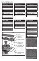
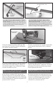
6b. ONLY FOR S-AG65/S-DG65/S-TIF65/S-
AG100 Install: Using a 2-1/4” hole saw, cut
a hole through the base of the PVC channel
at the desired outlet location along the
length of the channel.
6b. SOLO PARA S-AG65/S-DG65/S-TIF/S-
AG100 INSTALACION: Usando un 2-1/4” sier-
ra de perforación, corte un agujero a través
de la base del canal de PVC a la ubicación que
desea a lo largo de la longitud del canal.
Cordless Drill with
2¼” Hole Saw
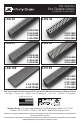
(B) PVC Channel –
G38/G100
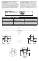
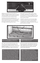
7. Dry t components before axing. Ax
the stop ends (C) to the channel using clear
PVC primer and PVC cement.
7. Poner una tapa de PVC a cada esquina del
canal usando imprimación PVC y cemento
de PVC.
(B) PVC Channel – G38/G65/G100
(C) Stop End – E38/E65/E100
Note: Do NOT ax channel or outlet sec-
tion to threaded nipple until step 9.
Tenga en cuenta: No pege el canal a la sec-
ción de salida al niple roscado hasta el paso 9.
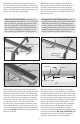
8. Screw threaded nipple (E) into top clamp
down plate of the drain body (F). Adjust to
the desired height. Turn clockwise to lower,
counter-clockwise to raise.
8. Enroscar niple roscado (E) en la sujeción
superior del drenaje (F). Adaptarla a la altura
que desea. Gire hacia la derecha para bajar,
hacia izquierda para subir.
9. Test t the combined PVC channel for
desired height onto the threaded nipple (E).
Ax the threaded nipple (E) to the underside
of the combined PVC channel using clear PVC
primer and PVC cement.
9. Pruebe y ajuste a la combinación de PVC
a la desea longitud en el threaded nipple (E).
Colocar el threaded nipple (E) en la parte
inferior del canal de PVC usando impri-
mación PVC y cemento de PVC.
(E) Threaded
Nipple - S50
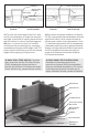
(F) 2” Throat Clamp Down
Drain Body* (Two Pieces)
Waterproong
Membrane
Mortar Bed
Suboor
(F1)
(F2)
(B) PVC Channel – G38
Desired Outlet
Location
32 Tooth per
Inch Blade
Hacksaw
(D) Outlet Section – S32
(B) PVC Channel – G38