
Installation Sheet

6
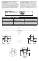
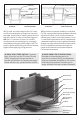
Note: Minimum height: 1⅝” Maximum
height with standard nipple (S50): 2¾”
Tenga en Cuenta: Altura Mínima: 1⅝” Altura
Máxima con niple: (S50): 2¾”
PVC Channel Assembly
Waterproong MembraneMortar BedSuboor
Shims
Lumber
Tile
Backer Board
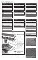
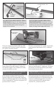
10. After dry, measure and cut a piece of
lumber to length and width of the PVC channel.
Insert the lumber into the channel during mor-
tar and tiling to prevent channel exing.
11. Measure the distance between the
waterproong and set PVC Channel assembly.
Cut two pieces of lumber to the measured
dimensions and place under the PVC Channel
for support while laying mortar bed.
10. Después que se seque, medir y cortar
una pieza de madera a la longitud y ancho
del canal de PVC. Insertar la madera en canal
durante el mortero y baldosas para prevenir
que el canal se doble.
11. Medir la distancia entre la impermeabi-
lización y colocar el canal. Corte dos piezas
de madera para medir las dimensiones y
coloque bajo el canal para soportar, mientras
que el mortero se instala.
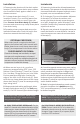
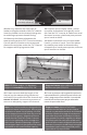
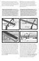
12. Create a mortar bed the length of the
channel on the waterproong membrane
and backll the underside of the channel and
ensure it is level. Use necessary amount of
mortar to adequately support the channel.
12. Crear un mortero a la longitud del canal en la
impermeabilización y rellena la parte inferior del
canal y asegura que este nivelado. Usa cantidad
necesaria de mortero para apoyar adecuada-
mente el soporte del canal.
Note: Site Sizable models are designed with
a nished neutral internal pitch. With proper
ventilation of waste line plumbing, the uid
of the charged channel will nd any point of
exit by force of gravity. Negative pressure
below the drain level will create a vacuum
to aid in the siphoning action through the
drain outlet. Based on Manning’s Equation
the designed depth of the channel has been
optimized for the specied ow capacity.
Tenga en cuenta: Nuestro Site-Sizable
modelos son diseñado con un tono interno
neutral, con adecuada ventilación de la línea de
residuos, el uido de la carga del canal encon-
trara todos los puntos de salida por la fuerza
de la gravedad, la presión negativa por debajo
del drenaje creara un vacío para ayudar en la
acción de sifón a través del agujero del drenaje.
Basada en la ecuación de Manning’s la longitud
deseada del canal ha sido optimizada para la
capacidad de ujo especicada.
*Not provided by Innity Drain kits
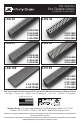
(E) Threaded Nipple -
S50
PVC Channel Assembly
(F) 2” Throat Clamp Down
Drain Body*(Two Pieces)
(F1)
(F2)