Infinity TM Burnout Furnaces OPERATOR’S MANUAL 115V, 60Hz Models
TABLE OF CONTENTS Introduction . . . . . . . . . . . . . . . . . . . . . . . . . . . . . . . . . . . . . . . . . . . . . . . . . . . . . . . . . . . . . . . .2 Warranty . . . . . . . . . . . . . . . . . . . . . . . . . . . . . . . . . . . . . . . . . . . . . . . . . . . . . . . . . . . . . . . . . .2 Safety Instructions . . . . . . . . . . . . . . . . . . . . . . . . . . . . . . . . . . . . . . . . . . . . . . . . . . . . . . . . . . . .2 Specifications . . . . . . . . . . . . . . . . . . . . . . . . . . .
INTRODUCTION Thank you for purchasing an Infinity Burnout Furnace. We have designed and manufactured this furnace using the latest in microcomputer technology to give you many years of dependable service. The controls on your new Infinity are different from those you may be used to on an ordinary burnout furnace. To ensure that your Infinity Burnout Furnace gives you the highest level of service, review and follow the guidelines outlined in this Operator’s Manual.
SPECIFICATIONS Electrical INFINITY M 115V 60Hz 8-1 3/4” rings or 2-3” rings Capacity Overall Dimensions Heating Chamber Dimensions 1150W 1610W 15-1 3/4” rings or 5-1 3/4” rings and 3-3” rings 10-3/4”W x 13-7/8”D x 18-3/4”H (27.3cm x 35.2cm x 47.6cm) 5-1/2”W x 5-1/4”D x 5-1/8”H (14.0cm x 13.3cm x 13.0cm) INFINITY L 115V 60Hz 14-1/2”W x 14-3/8”D x 18-3/4”H (36.8cm x 36.5cm x 47.6cm) 9-1/8”W x 5-1/4”D x 5-1/8”H (23.2cm x 13.3cm x 13.
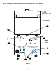
KEY PARTS IDENTIFICATION AND EXPLANATION DISPLAY DESCRIPTION 1. NIGHT TIME (DELAY START) Press to start a delayed program. The number entered is the time required for the program to be COMPLETED AND READY TO CAST. When a program is running, press to display the time remaining to complete the program. 2. START / STOP Press to start or stop a program. 3. ° FRONT PANEL (Figure 1) Press to increase a number. The longer the button is pressed, the faster the numbers change.
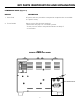
KEY PARTS IDENTIFICATION AND EXPLANATION Vent Tube Keep clear 6” zone around Vent Tube Heating Chamber 13 11 8 9 7 10 12 Front Panel 5 6 3 1 4 2 Figure 1 INFINITY M AND L IDENTIFICATION 5
KEY PARTS IDENTIFICATION AND EXPLANATION LOWER BACK PANEL (Figure 2) DISPLAY DESCRIPTION 1. Power Cord AC power cords are provided to correspond to receptacles that are available in a specific country. 2. Circuit Breaker Protects circuitry from electrical overload. - Black button will “pop out” if overload is present. - To reset, wait one minute and push black button into body of circuit breaker.
INSTALLATION UNPACK AND SET-UP 1. Unpack the contents of the box. Remove the following materials: A. Vent Tube - Remove from bubble wrap and insert in hole on top of furnace. B. Calibration Table Kit - Remove plastic bag containing two tablets and save for future use. C. Burnout Tray - Remove tray(s) from bubble wrap and install on the floor of the chamber. 2. Place the furnace in position allowing a minimum of 10 inches (25.4 cm) of air space on all sides. 3. Plug the power cord into a wall receptacle.
INSTALLATION TO TURN THE “BEEP” ON AND OFF (Figure 1) When a program is completed, 20 "beeps" sound every 15 minutes to remind the operator that the material is ready to cast. 1. Be sure the Infinity is in the idle mode - no program us running. ° 3. Use either of the ° ° 2. Press and (while holding) press PROGRAM NUMBER to display the status of the "beep." "ON" indicates the beep is active. "OFF" indicates the beep is inactive. to turn the "beeps" on or off. 4.
OPERATION PROGRAM AND OPERATE - ONE STAGE PROGRAM (Figure 1) ° 2. Press PROGRAM NUMBER. Use ° 1. Turn the power switch on. to display the desired program number (P1 - P30). ° ° 3. Press ENTER / REVIEW to select the displayed PROGRAM NUMBER. STAGE 1 and NIGHT TIME (DELAYED START) lights turn on. Enter to set the time required for the program to be completed and ready to cast (1 - 99hrs). ° ° 4. Press ENTER / REVIEW.
OPERATION PROGRAM AND OPERATE - TWO STAGE PROGRAM (Figure 1) 1. Follow One Stage Program, Steps 1 - 6. ° 2. Press ENTER / REVIEW. STAGE 1 light turns off, STAGE 2 and HEAT RATE lights turn on. Main Display shows four heat rate choices. Choose one: A. Select heat rate between 1°F - 30°F / min (1°C - 17°C / min) using . B. Select "FULL" to program maximum heat rate. C. Select "COOL" to program the furnace to cool to a selected temperature. D. Select "NO" to turn of STAGE 2, 3 and 4.
OPERATION PROGRAM AND OPERATE - THREE STAGE PROGRAM (Figure 1) 1. Follow Two Stage Program, Steps 1 - 4. ° ° 2. Press ENTER / REVIEW. STAGE 2 light turns off, STAGE 3 and HEAT RATE lights turn on. Main Display shows four heat rate choices. Choose one: A. Select heat rate between 1°F - 30°F /min (1°C - 17°C /min) using . B. Select "FULL" to program maximum heat rate. C. Select "COOL" to program the furnace to cool to a selected temperature. D. Select "NO" to turn of STAGE 3 and 4.
OPERATION PROGRAM AND OPERATE - FOUR STAGE PROGRAM (Figure 1) 1. Follow Three Stage Program, Steps 1 - 4. ° ° 2. Press ENTER/REVIEW. STAGE 3 light turns off, STAGE 4 and HEAT RATE lights turn on. Main Display shows four heat rate choices. Choose one: A. Select heat rate between 1°F - 30°F/min (1°C - 17°C/min) using . B. Select “FULL” to program maximum heat rate. C. Select “COOL” to program the furnace to cool to a selected temperature. D. Select “NO” to turn off Stage 4.
OPERATION REVIEW A PROGRAM (Figure 1) 1. Turn the power switch on. 2. Press PROGRAM NUMBER. ° ° 3. Press to select the program number to be reviewed. The PROGRAM NUMBER (P1 - P30) will appear on the Main Display. 4. The number of stages in the program are indicated by the STAGE lights next to the Main Display. 5. Press ENTER / REVIEW. NIGHT TIME (DELAY START) light turns on. The number of hours entered for the entire program to be completed and ready to cast appears on the Main Display.
OPERATION EDIT WHILE A PROGRAM IS RUNNING (Figure 1) The program number cannot be changed using ° NOTE: ° 1. To identify which program is running, press PROGRAM NUMBER. while the program is running. 2. To determine the time remaining for the completion of the program, press NIGHT TIME (DELAY START). The time remaining appears on the Main Display for 5 seconds. 3. Any individual parameter can be increased or decreased during the actual running of all 30 programs.
OPERATION SAMPLE ONE STAGE PROGRAM (To be completed and ready to cast in 24 hours) NIGHT TIME DELAY START HEAT RATE TEMP HOLD TIME 24:00 10°F (6°C) 1600°F (871°C) 1:00 STAGE 2 NO * * STAGE 3 NO * * STAGE 4 NO * * STAGE 1 * Though any number may appear, the unit is deactivated when “NO” is selected for the HEAT RATE. NOTE: To turn off STAGE 2,3 and 4, select “NO” for the HEAT RATE in STAGE 2. Press NIGHT TIME (DELAY START).
OPERATION SAMPLE THREE STAGE PROGRAM (Program with Cooling) HEAT RATE TEMP HOLD TIME STAGE 1 10°F (6°C) 600°F (316°C) 30 STAGE 2 20°F (11°C) 1600°F (871°C) 1:00 STAGE 3 NO * * STAGE 4 NO * * * Though any number may appear, the unit is deactivated when “NO” is selected for the HEAT RATE. To start immediately, press START / STOP. Follow the same programming procedures if a three or four stage program is desired. Press NIGHT TIME (DELAY START) to start an overnight burnout.
ERROR CODES NOTE: “Beeps” occur when the Error Code appears on the Main Display ERROR CODE DESCRIPTION PROBABLE CAUSE Er 1 INVALID ENTRY ERROR: STAGE, HEAT RATE and TEMP lights flash Er 2 TABLET TEMPERATURE CALIBRATION ERROR Er 3 ELECTRONICS MALFUNCTION Occurs when PC board hardware malfunctions. Er 4 OPEN THERMOCOUPLE Occurs if the thermocouple is open or the connecting wire(s) are broken or disconnected from the terminal board.
ERROR CODES ERROR CODE DESCRIPTION PROBABLE CAUSE Er 6 SHORTED THERMOCOUPLE OR DEFECTIVE HEATER PLATES Occurs if the thermocouple wires are shorted or the heater plates are defective causing Infinity to achieve a HEAT RATE of less than 6% of the maximum attainable HEAT RATE with full power applied to the heater plates for 5 minutes.
SERVICE CLEANING INSTRUCTIONS Clean exterior of furnace only by wiping unit with a damp cloth coated with a mild non abrasive cleaner. CAUTION: The INFINITY should be serviced only by qualified service technicians. Be sure to unplug the power cord and wait for the furnace to cool before performing any service operation. For help with operating or servicing your Jelrus equipment, please call Jelrus any time between 9:00am and 5:00pm Eastern time.
6. ° SERVICE When the tablet begins to melt or liquify at the edges, immediately press and hold. Then press ENTER/REVIEW. Your Infinity is now calibrated. Three “beeps” sound and “CAL” appears on the main display. Calibration Tablet Heating Chamber Ceramic Tray Casting Ring POWER FAILURE 1. If a power failure occurs, the Infinity memorizes the conditions prior to the loss of power. When the power returns, the Infinity returns to the proper point in the program. 2.
FIELD SERVICE REPLACEMENT OF HEATING PLATES REPLACEMENT PART NUMBERS 115V M (Set of 2) 33915 L Set of 2 Side Plates 33918 Set of 2 Rear Plates 33917 1. Remove the back panel of the furnace. 2. Remove the nuts which hold the heating plate wires to the power terminals and straighten the heating plate wires (Figure 4). 3. Open the furnace door and find the two ceramic sections at the front of the furnace chamber. Hold the furnace door partially open while removing the ceramic sections.
Figure 4 INFINITY WITH UPPER REAR PANEL REMOVED Rear Insulating Panel Jumper Thermocouple Heating Plate Wire Thermocouple Clamp Power Terminal Ceramic Insulating Bushing Insulating Filler Heater (Power) Leads INFINITY M Jumper Rear Insulating Panel Heating Plate Wire Thermocouple Power Terminal Thermocouple Clamp Ceramic Insulating Bushing Heater (Power) Leads Insulating Filler INFINITY L 22
FIELD SERVICE REPLACEMENT OF THE MAIN PC BOARD REPLACEMENT PART NUMBERS 115V M 15500-041 L 15500-541 1. Remove the front panel (Figure 5). 2. Note and record the color and location of each wire on the thermocouple terminals located on the Main PC Board. Remove both wires. 3. Remove the calibration jack connector (J1) from the Main PC Board by pulling straight up. 4. Remove five electrical connectors (BLACK, ORANGE, YELLOW, WHITE, GREEN) from the Main PC Board by pulling straight up on the connector.
Figure 5 INFINITY WITH FRONT PANEL / MAIN PC BOARD REMOVED Figure 5A OTHER COMPONENTS 24
FIELD SERVICE REPLACEMENT OF THE THERMOCOUPLE ASSEMBLY (PN 18913) 1. Remove the bottom front panel and the upper and lower rear panels of the furnace. (Note the position of the vent louvers on the rear panels.) 2. Note and record the color and location of the wires on the thermocouple terminals located on the Main PC Board (Figure 5). 3. Remove the thermocouple wires from the thermocouple terminals on the Main PC Board (Figure 5). 4.
FIELD SERVICE REPLACEMENT OF THE TRIAC (PN 15475) 1. Remove the lower rear panel (Figure 2). 2. Note and record the color and location of each of the three wires on the triac terminals (Figure 5A). Remove each of the three wires by pulling straight up on the connector. DO NOT PULL ON THE WIRES. 3. Remove the two nuts and screws that hold triac in place. Lift triac off the rear panel (Figure 5A). 4. There is an insulating pad located between triac and panel.
SPARE PARTS LIST PARTS FOR INFINITY M DESCRIPTION 115V Power Cord Kit-Japan & U.S.
SPARE PARTS LIST PARTS FOR INFINITY L DESCRIPTION 115V Power Cord Kit-Japan & U.S.
PROGRAM CARD FORMS Program # Metal(s) HEAT RATE TEMP Program # HEAT RATE HOLD TIME STAGE 1 STAGE 1 STAGE 2 STAGE 2 STAGE 3 STAGE 3 STAGE 4 STAGE 4 Program # Metal(s) HEAT RATE TEMP Program # STAGE 1 STAGE 2 STAGE 2 STAGE 3 STAGE 3 STAGE 4 STAGE 4 Program # Metal(s) HEAT RATE TEMP STAGE 1 STAGE 1 STAGE 2 STAGE 2 STAGE 3 STAGE 3 STAGE 4 STAGE 4 Program # Metal(s) HEAT RATE TEMP Program # STAGE 1 STAGE 1 STAGE 2 STAGE 2 STAGE 3 STAGE 3 STAGE 4 STAGE 4 29 TEMP HO
PROGRAM CARD FORMS Program # Metal(s) HEAT RATE TEMP Program # HEAT RATE HOLD TIME STAGE 1 STAGE 1 STAGE 2 STAGE 2 STAGE 3 STAGE 3 STAGE 4 STAGE 4 Program # Metal(s) HEAT RATE TEMP Program # STAGE 1 STAGE 2 STAGE 2 STAGE 3 STAGE 3 STAGE 4 STAGE 4 Program # Metal(s) HEAT RATE TEMP STAGE 1 STAGE 1 STAGE 2 STAGE 2 STAGE 3 STAGE 3 STAGE 4 STAGE 4 Program # Metal(s) HEAT RATE TEMP Program # STAGE 1 STAGE 1 STAGE 2 STAGE 2 STAGE 3 STAGE 3 STAGE 4 STAGE 4 30 TEMP HO
70 Cantiague Rock Road, Hicksville, NY 11801 Phone: 516-942-0202; Fax: 516-433-7684 TOLL FREE: 1-800-JELRUS-1 Jelrus International, a division of Air Techniques Inc., has been a leading manufacturer of dental laboratory equipment essential to the fabrication of porcelain caps, crowns and bridges for over thirty years. Innovative design and superior product performance are proven Jelrus trademarks. Jelrus International is a Division of: 70 Cantiague Rock Road P.O.