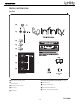
TSS-SUB4000 SERVICE MANUAL Infinity Systems Incorporated 250 Crossways Park Dr.
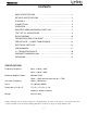
TSS-SUB4000 CONTENTS BASIC SPECIFICATIONS . . . . . . . . . ………………………………………….1 DETAILED SPECIFICATIONS . . . . . . . . . . . ………………………………….2 CONTROLS. ………………….. .. . …………………………………... . . . . . . .4 CONNECTIONS . . . . . . . . . . . ……….………………………………..…. . . . 5 OPERATION……. . . . . .. . . . . . . . .. .. . . . .. .. . . . . ….……… . . ... . . . . . . .6 EXPLODED VIEWS-MECHANICAL PARTS LIST….… . … . .. . . .. . … . ….7 TEST SET-UP & PROCEDURE……………………….. .. .. . . …………….. .9 BLOCK DIAGRAM. . . . ………………...
TSS-SUB4000 TSS-4000 subwoofer 300W Powered Sub/ Plate Amp LINE VOLTAGE US 120vac/60Hz EU 230vac/50-60Hz Asia 100vac/50Hz Parameter Amp Section Type (Class AB, D, other) Load Impedance (speaker) Rated Output Power THD@ Rated Power THD @ 1 Watt DC Offset Damping factor Input Sensitivity Line/Hi Level Input Phase Line Input Speaker/Hi Level Input Yes/No Yes No No Hi/Lo Line 108-132 207-264 90-110 Nom. 120 230 100 Unit Vrms Vrms Vrms Specification Unit QA Test Limits Conditions D 4 300 1 0.
TSS-SUB4000 Parameter Specification THD at Max. Output Power Output Volume Control Volume Control Pot Detent (center/#) Taper (lin/log) @ minimum setting Unit less than 10 % YES NO log A taoer no output Input/Output Phase Line Input vs. Hi Input Lo/Hi Input vs.
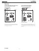
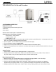
TSS-SUB4000 CONTROLS AND CONNECTIONS Rear Panel ¡ ™ £ ¢ § ¶ ∞ • ª ¡ Subwoofer Level (Volume) Control Room Adaptive Bass Optimization System Controls (see page 5) ™ Line-Level Inputs § R.A.B.O.S. Selector £ Normal/LFE Low-Pass Selector ¶ R.A.B.O.S. Level Adjustment ¢ Phase Switch • R.A.B.O.S. Bandwidth Adjustment ∞ Power Switch ª R.A.B.O.S.
TSS-SUB4000 CONNECTIONS If you have a Dolby* Digital or DTS® receiver/processor with a low-frequency-effects (LFE) output: If your receiver/processor has subwoofer outputs for the left and right channels: • Set Low-Pass Switch to Off. • Set Low-Pass Switch to On. NOTE: In this case, you do not need to use a Y connector. Simply connect the LFE output on your receiver/processor to either the left or right input on the subwoofer.
TSS-SUB4000 OPERATION Power On Low-Pass Selector Plug your subwoofer’s AC cord into a wall outlet. Do not use the outlets on the back of the receiver. If you have a Dolby Digital or DTS processor/receiver, the Crossover Frequency is set by the processor/receiver. Consult your owner’s manual to learn how to view or change this setting. In this case, the Low-Pass Selector £ should be set to “Off”. We strongly recommend this setup method.
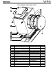
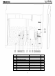
TSS-SUB4000 TSS-SUB4000 EXPLODED VIEW Ref # 1 2 3 4 5 6 7 8 9 10 11 12 13 14 Not Shown Description Part Number Qty Grille Woofer/Trim Ring Screw Trim Ring Woofer 12" (305mm) MMD Port Tube TSS-SUB4000 Amplifier Amplifier Screw TSS-SUB4000 Cabinet Rubber Foot Foot Screw Gasket LED Plastic Plate Aluminum Plate Power Transformer 329-120-05097-0VA 351-AM04030A893 213-120-05033-0BA 30PR14BW-DW01 249-HIPS-05021-0VA Not for Sale 352-FM04020D605 Not for Sale 320-RUB-05030-0BA 352-CM04025D604 333-EVA-05091-0WA
TSS-SUB4000 Ref # 1 2 3 4 5 6 7 8 9 10 11 Description Part Number Qty Screw Damping Main Mounting Bolt Tube Gasket Rubber Gasket Rubber Gasket Damping Power Transformer Nut Damping 352-CM03530D926 11 1 1 2 1 2 1 1 1 1 1 398-RUB-05093 336-RUB-05013 150-R1107008 8
TSS-SUB4000 TSS-SUB4000 Test Set Up and Procedure SYSTEM AURAL SWEEP TEST Equipment needed: • Function/signal generator/sweep generator • Multimeter • RCA cables General Unit Function (UUT = Unit Under Test) Switches/knobs on the amplifier faceplate: Phase switch – either position Low Pass switch – Off RABOS switch – Off 1. From the signal generator, Connect both right and left line level inputs (RCA jacks) – to signal generator and UUT. Use Y-cable if necessary from mono source. 2.
TSS-SUB4000 10
TSS-SUB4000 TSS-Sub4000 Testing Flow Chart yes Start Test protection Dc voltage check ±Vcc,±15V no OK no OK Check U107.R237 ±15Vcc ect yes Check transformer C168,C169,D123, D124,C170 Test limiter circuit yes no Power on check LED red &blue OK Check U106.Q107ect yes no OK Check vol module & connector cable& ±15V.ect Check THD output power, noise yes no OK Test frequency Response yes no OK Auto off Function Hi pot test Check U102,R124, C104,R125,C117.
TSS-SUB4000 NOTICE The main power transformer (toroid) part# 150-r1107008 in the TSS-SUB4000 is not mounted in the amplifier inside the amp cover, but mounted in the cabinet in a separate location. Replacement: To replace the power transformer, it is necessary to remove the woofer from the cabinet. The mounting bolt and transformer itself is mounted on an internal brace; both are accessible through the woofer opening. Instructions for woofer removal can be found on the exploded view, page 7.
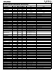
TSS-SUB4000 TSS-SUB4000 120V Electrical Parts List Part Number Description Qty Reference Designator MAIN PCB Resistors 110-12621j15 110-16102j26 110-16103j26 110-16153j26 110-16182j26 110-16222j26 110-16223j26 110-16274j26 110-16333j26 110-16391j26 110-16432j26 110-16472j26 110-16473j26 110-16683j26 122-14101j26 116-141r00j26x 116-161001f26 116-161002f26 116-161022f26 116-161301f26 116-161822f26 116-162001f26 116-162492f26 116-164320f26 116-166813f26 110-20152j20 113-500r1j10 116-142003f26 Resistor 62
TSS-SUB4000 Part Number Description Qty Reference Designator MAIN PCB Miscellaneous 109-1tsc103j0 162-10229004 171-udhss124d 175-1c02p01 175-1c06v01 175-1d02v01 thermister TSC05103J wire assy 220mm AWG28 relay 5A 24V UDH-SS124D coupling 2PIN PITCH=2.5mm coupling 6PIN PITCH=2.5mm coupling 2PIN PITCH=3.
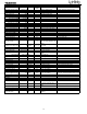
TSS-SUB4000 Part Number Description Qty Reference Designator INPUT/RABOS PCB Capacitors 129-a102j633 129-a103j633 129-a104j633 129-a223j633 129-a224j633 129-a473j633 130-2b102k503 130-2b221k503 metalized Capacitor 0.001uF 63V ± 5% MSC metalized Capacitor 10NF 63V metalized Capacitor 0.1U 63V ± 5% MSC metalized Capacitor 0.022U 63V ± 5% MSC metalized Capacitor 0.22uF 63V ± 5% MSC metalized Capacitor 0.
TSS-SUB4000 Part Number Description Qty Reference Designator CLASS D AMP PCB 141-c7223k50 141-d7104ka0 130-s1681kb03 132-104kb50 132-105kb50 SMD Capacitor 0.022uF 50V 10% 1206 X7R SMD Capacitor 0.1uF 100V 10% 1210 X7R disc Capacitor SL 680PF 200V mylar Capacitor 0.1U±10% 250V LS-10.mm MD mylar Capacitor 1uF 250V ±10% 1 4 1 1 1 C13 C12,C14,C18,C19 C20 C40 SMD I.C.
TSS-SUB4000 17
TSS-SUB4000 18
TSS-SUB4000 19
TSS-SUB4000 20
TSS-SUB4000 21
TSS-SUB4000 22
TSS-SUB4000 23
TSS-SUB4000 24
TSS-SUB4000 25
TSS-SUB4000 26
TSS-SUB4000 27
TSS-SUB4000 28
TSS-SUB4000 29
TSS-SUB4000 30
TSS-SUB4000 PACKAGE Ref # 1 2 3 4 5 6 7 8 9 10 Description Part Number Owner’s Manual Warranty Card Top/Bottom Packing Plastic Bag RABOS Kit Silica Gel Outer Carton n/a 15ft.