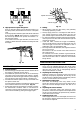
Impact Drill Model DV 20VB2 Handling instructions Note: Before using this Electric Power Tool, carefully read through these HANDLING INSTRUCTIONS to ensure efficient, safe operation. It is recommended that these INSTRUCTIONS be kept readily available as an important reference when using this power tool.
GENERAL OPERATIONAL PRECAUTIONS WARNING! When using electric tools, basic safety precautions should always be followed to reduce the risk of fire, electric shock and personal injury, including the following. Read all these instructions before operating this product and save these instructions. For safe operations: 1. Keep work area clean. Cluttered areas and benches invite injuries. 2. Consider work area environment. Do not expose power tools to rain. Do not use power tools in damp or wet locations.
SPECIFICATIONS Voltage (by areas)* Power input Speed change No load speed Steel Capacity Concrete Wood Full load impact rate Weight (without cord) (110V, 220V, 230V, 240V) 730 W* 1 0 – 1000 min–1 13 mm 20 mm 40 mm 8000 min–1 2 0 – 3000 min–1 8 mm 13 mm 25 mm 26000 min–1 2.2 kg *Be sure to check the nameplate on product as it is subject to change by areas. STANDARD ACCESSORIES (1) Chuck Wrench (Spec. only for keyed chuck) ........... 1 (2) Side Handle .....................................................
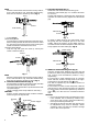
NOTE When the sleeve does not become loose any further, fix the side handle to ring, hold side handle firmly, then turn the sleeve to loosen by hand. (Fig. 4) Ring Loosen 7. Fixing the side handle (Fig. 7) Attach the side handle to the mounting part. Rotate the side handle grip in a clockwise direction to secure it. Set the side handle to a position that is suited to the operation and then securely tighten the side handle grip. Sleeve Side handle Side handle Loosen Tighten Fig. 4 䡬 Type B (Fig.
Change lever Stopper Speed control dial Low speed Impact Rotation High speed Switch trigger Fig. 9 9. High-speed/Low-speed changeover: Prior to changing speed, ensure that the switch is in the OFF position, and the drill has come to a complete stop. To change speed, rotate the gear shift dial as indicated by the arrow in Fig. 10. The numeral “1” engraved on the drill body denotes low speed, the numeral “2” denotes high speed.
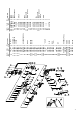
. Service parts list CAUTION: Repair, modification and inspection of Hitachi Power Tools must be carried out by a Hitachi Authorized Service Center. This Parts List will be helpful if presented with the tool to the Hitachi Authorized Service Center when requesting repair or other maintenance. In the operation and maintenance of power tools, the safety regulations and standards prescribed in each country must be observed.
Item No. 1 2 3 1 3 2 3 3 4 1 4 2 5 6 7 8 9 10 11 12 1 12 2 13 14 1 14 2 15 16 17 18 1 18 2 19 20 21 22 23 24 25 26 27 28 1 28 2 29 30 31 32 33 1 33 2 33 3 34 35 Code No. No. Used Remarks 995-344 1 M6×25 ____ 1 321-814 1 13VLRB-D 319-546 1 13VLRE-N 316-280 1 13VLN 322-857 1 322-866 1 939-556 1 322-851 1 620-2DD 1 6202DDCMPS2L 322-850 1 984-101 1 959-150 1 D6.
Hitachi Koki Co., Ltd. 601 Code No.