RS232 Command and Control Guide Regulatory models: W60, W61 010-0763-00 DISPERINDAG No. 0287/1.824.51/09.
This page left blank intentionally
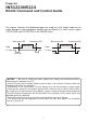
Projector IN5122/IN5124 RS232 Command and Control Guide The signals listed on the following pages are used for initial setup, however the signal timings of some computer models may be different. In such a case, adjust V POSITION and H POSITION in the IMAGE menu. Back porch (B) Front porch (D) Back porch (b) Active video (C) Data H. Sync. Active video (c) Data V. Sync.
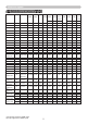
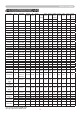
Initial set signals IN5122 Computer Mode Table Resolution Freq Standard DotCLK fH fV (Hz) H Total H Res H Sync H Back V Total (MHz) (KHz) (Pixels) (Pixels) (Pixels) Porch V Res V Sync V Back (Lines) (Lines) (Lines) 28.322 31.469 70.087 C A B 720 108 54 c a b 2 35 70 VESA-DMT 640x480 60 VESA-DMT 25.175 31.469 59.940 800 640 96 48 525 480 2 33 640x480 67 Apple-Mac 30.240 34.970 66.670 864 640 64 96 525 480 3 39 640x480 72 VESA-DMT 31.500 37.861 72.
Initial set signals IN5124 Computer Mode Table Resolution Freq Standard DotCLK fH (MHz) (KHz) H Res H Sync H Back V Total fV (Hz) V Res V Sync V Back H Total (Pixels) (Pixels) Porch (Lines) (Lines) (Lines) Porch (Lines) (Pixels) (Pixels) C A B c a b 720x400 70 VESA-DMT 28.322 31.469 70.087 900 720 108 54 449 400 2 35 640x480 60 VESA-DMT 25.175 31.469 59.940 800 640 96 48 525 480 2 33 640x480 67 Apple-Mac 30.240 34.970 66.
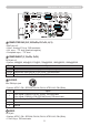
Connection to the ports Connection to the ports NOTICE ►Use the cables with straight plugs, not L-shaped ones, as the input ports of the projector are recessed. ►Only the signal that is input from the COMPUTER IN1 or IN2 can be output from the MONITOR OUT port. A B A COMPUTER IN1, B MONITOR OUT D-sub 15pin mini shrink jack • Video signal: RGB separate, Analog, 0.7Vp-p, 75Ω terminated (positive) • H/V. sync. signal: TTL level (positive/negative) • Composite sync.
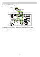
Connection to the ports (continued) C E F D C COMPUTER IN2 (G/Y, B/Cb/Pb, R/Cr/Pr, H, V) • BNC jack x 5 • Video : Analog 0.7Vp-p, 75Ω terminator • H/V, sync, : TTL level (positive/negative) • Composite sync, : TTL level D COMPONENT (Y, Cb/Pb, Cr/Pr) RCA jack x3 • System: 480i@60, 480p@60, 576i@50, 720p@50/60, 1080i@50/60, 1080p@50/60 Port Y Signal Component video Y, 1.0±0.1Vp-p with composite sync, 75Ω terminator Cb/Pb Component video Cb/Pb, 0.7±0.1Vp-p, 75Ω terminator Cr/Pr Component video Cr/Pr, 0.7±0.
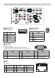
Connection to the ports (continued) G L H M I J K G HDMI 2 • Type :Digital audio/video connector • Audio signal : Linear PCM (Sampling rate; 32/44.1/48 kHz) Pin 1 2 3 4 5 6 7 Signal 1 Pin Signal Pin 8 9 10 11 12 13 14 T.M.D.S. Data0 Shield T.M.D.S. Data0 T.M.D.S. Clock + T.M.D.S. Clock Shield T.M.D.S. Clock CEC Reserved(N.C. on device) 15 16 17 18 19 T.M.D.S. Data2 + T.M.D.S. Data2 Shield T.M.D.S. Data2 T.M.D.S. Data1 + T.M.D.S. Data1 Shield T.M.D.S. Data1 T.M.D.S.
Connection to the ports (continued) N O Q P N USB TYPE A O USB TYPE B USB A type jack Pin 3 4 2 +5V 2 - Data 3 + Data 4 Ground Pin Signal 1 +5V 2 - Data 3 + Data 4 Ground P CONTROL D-sub 9pin plug • About the details of RS-232 communication, please refer to the section "RS-232 Communication".
Connection to the ports (continued) To input SCART RGB signal; ex. SCART connector (jack) SCART SCART cable (plug) RCA plugs To input SCART RGB signal to the projector, use a SCART to RCA cable. Connect the plugs refer to above example. For more reference, please consult your dealer.
RS-232 Communication RS-232 Communication When the projector connects to the computer by RS-232 communication, the projector can be controlled with RS-232 commands from the computer. For details of RS-232 commands, refer to RS-232 Communication / Network command table (&16). Connection 1. Turn off the projector and the computer. the projector's CONTROL port and the computer's RS-232 port with 2. Connect a RS-232 cable (cross).
Command Control via the Network Command Control via the Network When the projector is connected to the network, the projector can be controlled with RS-232 commands from the computer with a web browser. For RS-232 command information, refer to the RS-232 Communication / Network command table (&16). Connection 1. Turn off the projector and the computer. Connect the projector's LAN port and the computer's LAN port with a LAN 2. cable.
Command Control via the Network (continued) Communication Port The following port is assigned for command control. TCP #23 Configure the following items from a web browser when command control is used. Port Settings Port open Click the [Enable] check box to open [Network Control Port1 (Port: 23)] to use TCP #23. Default setting is “Enable”. Authentication Click the [Enable] check box for the [Authentication] setting when authentication is required. Default setting is “Disable”.
Command Control via the Network (continued) RS-232 Commands IMPORTANT: When formatting commands sent from a control system or computer, enclose commands in parentheses “(“ and “)”. When entering custom commands into Scheduled Tasks in the projector’s web interface, enclose commands in less than/ greater than symbols “<” and “>” instead. Communication Configuration Visit our website for additional RS-232 settings and information.
Command Control via the Network (continued) A write request example: (AAA####) where (starts the command AAA denotes the command #### denotes the value to be written (leading zeros not necessary) ) ends the command Some commands have ranges, while others are absolute. If a number greater than the maximum range is received, it is automatically set to the maximum number for that function. If a command is received that is not understood, a "?" is returned. With absolute settings, "0" is off, 1-9999 is on.
Network Bridge Communication Network Bridge Communication This projector is equipped with NETWORK BRIDGE function. When the projector connects to the computer by LAN communicaton, an external device that is connected with this projector by RS-232 communication can be controlled from the computer as a network terminal. For details, see the 6. Network Bridge function in the Network Guide. Connection the computer's LAN port and the projector's LAN port with a LAN 1. Connect cable.
Network Bridge Communication Communication settings For communication setting, use the OPTION - SERVICE - COMMUNICATION menu.
RS-232 Communication / Network command table RS-232 Communication / Network command table Function Command RW Min BASIC MENU Max Default ARZ RW 0 6 0 AVK W 0 1 n/a DKH DKV RW RW 38 38 218 218 128 128 CNE RW 0 1 0 CN1 RW 0 511 (IN5122) 0 639 (IN5124) 1 CN2 RW 0 550 0 1 Corner Correction Top Right corner CN3 -H RW 0 511 (IN5122) 0 639 (IN5124) 1 CN4 RW 0 550 0 1 CN5 RW 0 511 (IN5122) 0 639 (IN5124) 1 CN6 RW 0 550 0 1 CN7 RW 0 511 (IN5122) 0 639 (IN5
RS-232 Communication / Network command table (continued) Function Presets 1: User 5: Presentation 7: Video 10: Bright 11: Whiteboard 12: Blackboard 13: Greenboard 15: Dynamic Low Power 0: Disable 1: Enable Ceiling 0: Disable 1: Enable Rear 0: Disable 1: Enable Basic Menu Reset 1: Execute Reset Filter Hours 1: Reset Language 0: English 1: French 2: German 3: Italian 5: Korean 6: Norwegian 7: Portuguese 8: Russian 9: Simplified Chinese 10: Spanish 11: Traditional Chinese 12: Swedish 13: Dutch 14: Polish 15: T
RS-232 Communication / Network command table (continued) Function Gamma 32: 1 Default 16: 1 Custom 33: 2 Default 17: 2 Custom 34: 3 Default 18: 3 Custom 35: 4 Default 19: 4 Custom 36: 5 Default 20: 5 Custom 37: 6 Default 21: 6 Custom Gamma Pattern 0: Off 1: 9 steps gray scale 2: 15 steps gray scale 3: Ramp Gamma Custom-1 Point 1 Gamma Custom-1 Point 2 Gamma Custom-1 Point 3 Gamma Custom-1 Point 4 Gamma Custom-1 Point 5 Gamma Custom-1 Point 6 Gamma Custom-1 Point 7 Gamma Custom-1 Point 8 Gamma Custom-2 Point
RS-232 Communication / Network command table (continued) Function Gamma Custom-4 Point 7 Gamma Custom-4 Point 8 Gamma Custom-5 Point 1 Gamma Custom-5 Point 2 Gamma Custom-5 Point 3 Gamma Custom-5 Point 4 Gamma Custom-5 Point 5 Gamma Custom-5 Point 6 Gamma Custom-5 Point 7 Gamma Custom-5 Point 8 Gamma Custom-6 Point 1 Gamma Custom-6 Point 2 Gamma Custom-6 Point 3 Gamma Custom-6 Point 4 Gamma Custom-6 Point 5 Gamma Custom-6 Point 6 Gamma Custom-6 Point 7 Gamma Custom-6 Point 8 Color Temperature 0: 1 High 1: 1
RS-232 Communication / Network command table (continued) Function Color Temperature - 6 Blue Gain Color Temperature - 1 Red Offset Color Temperature - 2 Red Offset Color Temperature - 3 Red Offset Color Temperature - 4 Red Offset Color Temperature - 5 Red Offset Color Temperature - 6 Red Offset Color Temperature - 1 Green Offset Color Temperature - 2 Green Offset Color Temperature - 3 Green Offset Color Temperature - 4 Green Offset Color Temperature - 5 Green Offset Color Temperature - 6 Green Offset Color
RS-232 Communication / Network command table (continued) Function Aspect Ratio 0: Auto 1: Native (IN5124 Only) 2: 4:3 3: 16:9 6: 16:10 Overscan 0: Off 1: Zoom 2: Crop Command RW Min ADVANCED MENU: IMAGE Max Default Step ARZ RW 0 6 0 OVS RW 0 2 0 Vertical Position VPS RW if def<128: 0 else: def -128 def +128 auto 1 Horizontal Position HPS RW Def:+128 auto 1 Phase MSS RW 63 0 1 Tracking MTS RW Def:128 0 def: -384 def: +384 auto 2 Auto Image 0: n/a 1: enable AIM W 0
RS-232 Communication / Network command table (continued) Function S-Video Standard 0: Auto 1: NTSC 2: PAL 3: SECAM 4: NTSC4.
RS-232 Communication / Network command table (continued) Function Corner Correction all corners Reset 0: n/a 1: enable Side Correction Left Gain Side Correction Right Gain Command RW Min Max Default CNR RW 0 1 SC1 SC2 RW RW 98 Side Correction V Position SC3 RW 0 Side Correction Top Gain Side Correction Bottom Gain SC4 SC5 RW RW 98 158 158 768 (IN5122) 800 (IN5124) 158 158 Side Correction H Position SC6 RW 0 SCR W 0 1 n/a LPE RW 0 1 0 CEL RW 0 1 0 REA RW 0 1 0 SP
RS-232 Communication / Network command table (continued) Function Monitor Out for Source 5 (HDMI) 1: Computer in 1 2: Computer in 2 255: Off Monitor Out for Source 6 (Component) 1: Computer in 1 2: Computer in 2 255: Off Monitor Out for Source 7 (S-Video) 1: Computer in 1 2: Computer in 2 255: Off Monitor Out for Source 8 (Video) 1: Computer in 1 2: Computer in 2 255: Off Monitor Out for Standby 1: Computer in 1 2: Computer in 2 255: Off Command RW Min Max Default SM5 RW 1 255 1 SM6 RW 1 255
RS-232 Communication / Network command table (continued) Function Audio for Source 0 (Computer in 1) 0: Audio 1 1: Audio 2 2: Audio 3 5: Mute Audio for Source 1 (Computer in 2) 0: Audio 1 1: Audio 2 2: Audio 3 5: Mute Audio for Source 2 (LAN) 0: Audio 1 1: Audio 2 2: Audio 3 5: Mute Audio for Source 3 (USB Type A) 0: Audio 1 1: Audio 2 2: Audio 3 5: Mute Audio for Source 4 (USB Type B) 0: Audio 1 1: Audio 2 2: Audio 3 5: Mute Audio for Source 5 (HDMI) 0: Audio 1 1: Audio 2 2: Audio 3 4: HDMI Audio 5: Mute A
RS-232 Communication / Network command table (continued) Function HDMI Noise Cancel 0: Disable 1: Enable MIC Level 0: Low 1: High MIC Volume Command RW Min Max Default Step HNC RW 0 1 1 MIK RW 0 1 0 MIC RW 0 48 24 1 1 1 ADVANCED MENU: SCREEN Menu Positon H Menu Positon V Blank Screen 0: Blue 3: Black 4: white 5: Factory Logo 6: SnapShot Startup Logo 0: Factory Logo 1: Snapshot 2: Blank Screen Capture Lock 0: Off 1: On Display Messages 0: Disable 1: Enable Ruled Lines 0: Lines on White
RS-232 Communication RS-232/ Communication Network command / Network table (continued) command table (continued) Function Auto Power 0: Disable 1: Enable USB Type B 0: Mouse 1: USB Display Custom Key (Effect) 0: Blank 1: Mute 2: Aspect Ratio 3: Source 4: Auto Image 5: Freeze 6: Magnify 7: Source Info 8: Service Info 15: AV Mute 18: Ruled Lines 19: Slideshow 20: MyImage 21: Messenger 22: Auto Keystone 23: Active Iris 24: Re Source 1 0: Computer in 1 1: Computer in 2 2: LAN 3: USB Type A 4: USB Type B 5: HDMI
RS-232 RS-232Communication Communication/ /Network Networkcommand commandtable table(continued) (continued) Function Source 4 0: Computer in 1 1: Computer in 2 2: LAN 3: USB Type A 4: USB Type B 5: HDMI 6: Component 7: S-Video 8: Video Power-up Source 0: Computer in 1 1: Computer in 2 2: LAN 3: USB Type A 4: USB Type B 5: HDMI 6: Component 7: S-Video 8: Video Command RW Min Max Default SR4 RW 0 8 8 DSC RW 0 8 0 Step ADVANCED MENU: OPTION (SERVICE) Auto Image Mode 0: Disable 1: Fast 2: Fine
RS-232 Communication / Network command table (continued) Function My Image Display 0: Off 1: Image-1 2: Image-2 3: Image-3 4: Image-4 My Image Delete Image-1 1: delete My Image Delete Image-2 1: delete My Image Delete Image-3 1: delete My Image Delete Image-4 1: delete AMX Device Discovery Enable 0: Disable 1: Enable Network Restart 1: restart Command RW Min Max Default MIF RW 0 4 0 MD1 W 0 1 n/a MD2 W 0 1 n/a MD3 W 0 1 n/a MD4 W 0 1 n/a AMX RW 0 1 0 NTR W 0 1 n/a St
RS-232 Communication / Network command table (continued) Function Freeze 0: Off 1: On Command FRZ RW RW Min 0 Max Default 1 0 INFOCUS UNIQUE About (Source Info) 0: n/a 1: enable Lamp Lit 0: not lit 1: lit Number of Lamp Resets Lamp Total On Time (All Bulbs) Time In Hours Last Bulb1 Lasted Time In Hours Last Bulb2 Lasted Time In Hours Last Bulb3 Lasted Lamp Hours Filter Hours Unit Total Time On Error Status 0: No Error 1: Lamp won't strike 2: reserved 3: Lamp unexpectedly goes out 4: Fan failure 5: O
PJLink command PJLink command Commands Control Description POWR Power Control POWR ? Power Status inquiry INPT Input Source selection INPT ? Input Source inquiry AVMT AV Mute AVMT ? AV Mute inquiry (continued on next page) Parameter or Response 0 = Standby 1 = Power On 0 = Standby 1 = Power On 2 = Cool Down 11 = COMPUTER IN 1 12 = COMPUTER IN 2 21 = COMPONENT 22 = S-VIDEO 23 = VIDEO 31 = HDMI 41 = USB TYPE A 51 = LAN 52 = USB TYPE B 11 = COMPUTER IN 1 12 = COMPUTER IN 2 21 = COMPONENT 22 = S
PJLink command (continued) Commands ERST ? Control Description Error Status inquiry LAMP ? Lamp Status inquiry INST ? Input Source List inquiry NAME ? Projector Name inquiry INF1 ? INF2 ? INFO ? CLSS ? Manufucturer's Name inquiry Model Name inquiry Parameter or Response 1st byte: Refers to Fan error; one of 0 to 2 2nd byte: Refers to Lamp error; one of 0 to 2 3rd byte: Refers to Temperature error; one of 0 to 2 4th byte: Refers to Cover error; one of 0 to 2 5th byte: Refers to Filter error; one