Specifications
Manuals
Brands
Infocus Manuals
Projectors
IN5312A
41
42
43
44
45
46
47
48
49
50
Table Of Contents
Getting Started
Packing Checklist
Views of Projector Parts
Front-angled View
Top view—On-screen Display (OSD) buttons
Rear view
Bottom view
Remote Control Parts
Setup and Operation
Inserting the Remote Control Batteries
Installing or Removing the Optional Lens
Removing the Existing Lens From the Projector
Installing the New Lens
Starting and Shutting down the Projector
Adjusting the Projector Level
Adjusting Projected Image Position Using Shift
Adjusting the vertical image position
Adjusting the horizontal image position
Shift Range Diagram
Adjusting Zoom, Focus and Keystone
Adjusting the Volume
On-Screen Display (OSD) Menu Settings
OSD Menu Controls
Navigating the OSD
Setting the OSD Language
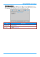
OSD Menu Overview
Image Menu
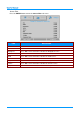
Computer Menu
Advanced Feature
Color Manager
Settings 1 Menu
Audio
Advanced 1 Feature
3D Setting
Advanced 2 Feature
Settings 2 Menu
Status
Advanced 1 Feature
Lamp Hour Reset
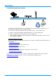
Network
Advanced 2 Feature
Source Filter
Maintenance and Security
Replacing the Projection Lamp
Resetting the Lamp Timer
Cleaning the Projector
Cleaning the Lens
Cleaning the Case
Troubleshooting
Common Problems and Solutions
Tips for Troubleshooting
LED Error Messages
Image Problems
Lamp Problems
Remote Control Problems
Audio Problems
Having the Projector Serviced
HDMI Q & A
Specifications
Specifications
Projection Distance vs. Projection Size (1080P)
Projection Distance and Size Table
Standard projection lens: TR: 1.54– 1.93; offset=10%
Long throw projection lens: TR: 1.93– 2.9; offset=10%
Short throw projection lens: TR: 0.77; offset=10%
Projection Distance vs. Projection Size (XGA)
Projection Distance and Size Table
Standard projection lens: TR: 1.6~2; offset=0%
Long throw projection lens: TR: 2~3; offset=0%
Short throw projection lens: TR: 0.8; offset=0%
Timing Mode Table
Projector Dimensions
Regulatory Compliance
FCC Warning
Canada
WEEE
Safety Certifications
Appendix I
Serial Communication
—
42
—
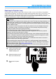
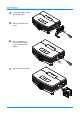
4.
Loosen the captive screw
on the lamp cover
.
5.
Pull up and remove the
cover.
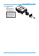
6.
Use a screwdriver to
loosen
the
two captive
screws
from
the lamp
module.
7.
Pull out the lamp module.
1
...
...
47
48
49
50
51
...
...
68