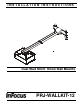
INSTALLATION INSTRUCTIONS Instrucciones de instalación Installationsanleitung Instruções de Instalação Istruzioni di installazione Installatie-instructies Instructions d´installation Dual Stud Short Throw Wall Mounts Spanish Product Description German Product Description Portuguese Product Description Italian Product Description Dutch Product Description French Product Description PRJ-WALLKIT-12
PRJ-WALLKIT-12 Installation Instructions DISCLAIMER InFocus and its affiliated corporations and subsidiaries (collectively "InFocus"), intend to make this manual accurate and complete. However, InFocus makes no claim that the information contained herein covers all details, conditions or variations, nor does it provide for every possible contingency in connection with the installation or use of this product.
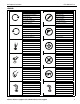
Installation Instructions PRJ-WALLKIT-12 LEGEND Tighten Fastener Pencil Mark Apretar elemento de fijación Marcar con lápiz Befestigungsteil festziehen Stiftmarkierung Apertar fixador Marcar com lápis Serrare il fissaggio Segno a matita Bevestiging vastdraaien Potloodmerkteken Serrez les fixations Marquage au crayon Loosen Fastener Drill Hole Aflojar elemento de fijación Perforar Befestigungsteil lösen Bohrloch Desapertar fixador Fazer furo Allentare il fissaggio Praticare un foro B
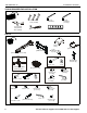
PRJ-WALLKIT-12 Installation Instructions TOOLS REQUIRED FOR INSTALLATION 1/2" (12.7mm) 7/16" (11.2mm) 1/2" (12.7mm) 3/8" (9.5mm) 7/32" (5.
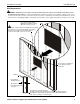
Installation Instructions PRJ-WALLKIT-12 Site Requirements WARNING: IMPROPER INSTALLATION CAN LEAD TO EQUIPMENT FALLING CAUSING SERIOUS PERSONAL INJURY OR DAMAGE TO EQUIPMENT! The figure below identifies the minimum requirements for installation of display mounts onto a steel stud structure. If the structure or its components do not meet these requirements contact the mount manufacturer for specific instructions before attempting installation.
PRJ-WALLKIT-12 Installation Instructions Assembly and Installation The PRJ-WALLKIT-12 short throw projector mounts can be mounted to concrete, concrete block, wood studs or steel studs. They can be mounted to studs up to 16" apart. For studs more than 16" apart, the PRJ-WALLADPT-24 accessory (not evaluated and tested by Underwriters Laboratories®) can be used to mount projector.
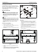
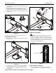
Installation Instructions 5. PRJ-WALLKIT-12 Install four 5/16 x 2-1/2" hex head lag screws (J) through four 5/16" washers (K), holes of mounting bracket and into drilled holes. (See Figure 4) 5. Hold metal channel on anchor (M) flat alongside plastic straps and slide channel through hole. (See Figure 6) Drywall 5 (J) x 4 Plastic Straps 5 (K) x 4 (M) x 4 (B) Figure 6 6. 7.
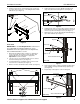
PRJ-WALLKIT-12 Installation Instructions 10. Place wall bracket over anchors and align mounting holes in wall bracket with holes in anchors. (See Figure 9) 2. Slide lower plate onto cross bracket on wall bracket. (See Figure 11) 11. Insert 1/4-20 x 1-3/4" Phillips pan head screws (L) through 1/4" washer (N), corresponding mounting hole on wall bracket and into anchor (M) and tighten until flush against mount. DO NOT overtighten! (See Figure 9) (B) 12. Repeat Step 11 for remaining 3 mounting holes.
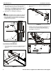
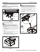
Installation Instructions PRJ-WALLKIT-12 4. Loosen two bolts on either side of pitch adjustment screw. (See Figure 13) 5. Adjust pitch adjustment screw until mount is at desired pitch level. Turn clockwise to raise mounting level or turn counterclockwise to lower mounting level. (See Figure 13) 6. Tighten two bolts on either side of pitch adjustment screw. (See Figure 13) raise 5 2 (C) lower 4 or 6 (U) x 2 2 Figure 15 Projector Installation Figure 13 7.
PRJ-WALLKIT-12 2. Installation Instructions Install four #10-24 x 1-3/8" Phillips pan machine screws (X) through projector mount holes and into mounting plate. (See Figure 17) WARNING: IMPROPER INSTALLATION CAN LEAD TO PROJECTOR FALLING RESULTING IN SERIOUS PERSONAL INJURY OR DAMAGE TO EQUIPMENT. Make certain mounting slots in projector mount slide under thumb screws and that screws are seated in the back of slots.
Installation Instructions PRJ-WALLKIT-12 Projector Mount Adjustments Yaw Adjustment 1. Loosen yaw adjustment locking screw using a #2 Phillips screwdriver. (See Figure 20) 2. Turn Yaw micro-adjustment screw right or left using a #2 Phillips screwdriver until image is properly aligned on target. (See Figure 20) 3. 1 3 Tighten Yaw adjustment locking screw using a #2 Phillips screwdriver. (See Figure 20) 2 1 3 2 Figure 21 Roll Adjustment 2 1.
PRJ-WALLKIT-12 Installation Instructions 4. Cable Management (Optional) Remove cable management covers (if necessary) from short throw projector arm. (See Figure 25) In most cases, cable management covers will NOT need to be removed in order to route cables from projector to the wall mount. But for some thick cables, removing the covers may be necessary. (bottom view) Removing Mount Covers 1. Remove and save two 8-32 x 1/2" Phillips pan head screws from upper cover. (See Figure 23) 2.
Installation Instructions • 7. PRJ-WALLKIT-12 Routing Cables from Above (Step 7) Thread cables down through a surface mount cable accessory (not included), then behind and into the wall bracket. (See Figure 28) Proceed to Step 8 9. (Optional) Cables can be tied to inside of projector’s front cover using cable ties (not included). Route cables near front cover and wrap cable tie through slots on front cover and around cables.
PRJ-WALLKIT-12 Installation Instructions Adjustments Installation of Wall Bracket Covers NOTE: If security screws are going to be used, use the security screws (R) to install wall bracket covers. See Security Screw Installation section for details. 1. Place wall bracket top covers (E) over top of each wall bracket arm. (See Figure 32) 1 (E) x 2 3 (F) x 2 Bracket Width Adjustment 1. Loosen two flat head cap screws on wall bracket. (See Figure 34) 2.
Installation Instructions PRJ-WALLKIT-12 2. Loosen two bolts on either side of pitch adjustment screw. (See Figure 36) 3. Adjust pitch adjustment screw until mount is at desired pitch level. Turn clockwise to raise mounting level or turn counterclockwise to lower mounting level. (See Figure 36) IMPORTANT ! : The mount covers need to be removed before proceeding with lateral shift adjustment. NOTE: Remove mount covers from the mount following 4.
PRJ-WALLKIT-12 2. Installation Instructions Install eight #8-32 x 1/2" button head security screws (R) into holes in wall bracket covers. (See Figure 40) 2 Stop Bracket 1. Remove two bolts holding stop bracket in place on underside of short throw projector mount. (See Figure 42) (R) x 8 Stop bracket (Projector arm not shown) 1 x2 Figure 40 Figure 42 Mount Covers 1. Remove two #8-32 x 1/2" Phillips pan machine screws (U) holding mount covers on projector arm. (See Figure 41) 2.
Installation Instructions 2. Remove one of four bolts from adapter plate. (See Figure 44) PRJ-WALLKIT-12 Reinstall projector to mount. Refer to Projector Installation to Mount section for details. WARNING: It is important to replace adapter plate bolts ONE AT A TIME or adapter plate could fall from mount during installation! Adapter plate x 4 (one at a time) 2 Figure 44 3. Install one 1/4-20 x 3/4" button head security screw (Q) into hole vacated by removing bolt in Step 2 and into plastic spacer.
PRJ-WALLKIT-12 18 Installation Instructions Visit the InFocus support site at www.infocus.
Installation Instructions Visit the InFocus support site at www.infocus.
PRJ-WALLKIT-12 Installation Instructions InFocus Corporation 13190 SW 68th Parkway, Ste 200 Portland, OR 97223 8800-002229 Rev00 2012 InFocus Corporation www.infocus.