INSTALLATION INSTRUCTIONS Instrucciones de instalación Installationsanleitung Instruções de Instalação Istruzioni di installazione Installatie-instructies Instructions d´installation Dual Stud Short Throw Wall Mounts Spanish Product Description German Product Description Portuguese Product Description Italian Product Description Dutch Product Description French Product Description SP-WALLKIT-02
SP-WALLKIT-02 Installation Instructions DISCLAIMER InFocus and its affiliated corporations and subsidiaries (collectively "InFocus"), intend to make this manual accurate and complete. However, InFocus makes no claim that the information contained herein covers all details, conditions or variations, nor does it provide for every possible contingency in connection with the installation or use of this product.
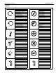
Installation Instructions SP-WALLKIT-02 LEGEND Tighten Fastener Pencil Mark Apretar elemento de fijación Marcar con lápiz Befestigungsteil festziehen Stiftmarkierung Apertar fixador Marcar com lápis Serrare il fissaggio Segno a matita Bevestiging vastdraaien Potloodmerkteken Serrez les fixations Marquage au crayon Loosen Fastener Drill Hole Aflojar elemento de fijación Perforar Befestigungsteil lösen Bohrloch Desapertar fixador Fazer furo Allentare il fissaggio Praticare un foro Be
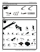
SP-WALLKIT-02 Installation Instructions TOOLS REQUIRED FOR INSTALLATION 5/32" (included) (security) 3/16" (included) 1/2" (12.7mm) 3/8" (9.5mm) 7/32" (5.6mm) #2 1/2" (12.7mm) 7/16" (11.
Installation Instructions SP-WALLKIT-02 Site Requirements WARNING: IMPROPER INSTALLATION CAN LEAD TO EQUIPMENT FALLING CAUSING SERIOUS PERSONAL INJURY OR DAMAGE TO EQUIPMENT! The figure below identifies the minimum requirements for installation of display mounts onto a steel stud structure. If the structure or its components do not meet these requirements contact the mount manufacturer for specific instructions before attempting installation.
SP-WALLKIT-02 Installation Instructions Assembly and Installation Wood Studs The SP-WALLKIT-02 short throw projector mounts can be mounted to concrete, concrete block, wood studs or steel studs. They can be mounted to studs up to 16" apart. For studs more than 16" apart, the SP-WALLADPT-24 accessory (not evaluated and tested by Underwriters Laboratories®) can be used to mount projector. 1. Determine mounting location on wall. Use a stud finder to locate studs.
Installation Instructions SP-WALLKIT-02 Steel Studs IMPORTANT ! : See Site Requirements section before proceeding with Steel Studs installation to ensure installation site meets requirements! The drywall must have a minimum thickness of 1/2"! 1. 2. 3. 4. 5. Steel Stud Drywall Determine mounting location on wall. Use stud finder to locate steel studs. For studs less than 16" apart, mounting brackets will have to be adjusted. See Adjustments section for details.
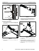
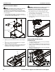
SP-WALLKIT-02 Installation Instructions Steel Stud (A) Drywall (Q) x 4 12 (B) (N) x 4 2 (B) Figure 11 Anchor Metal Channel 3. SIDE VIEW Figure 9 Install two 1/4-20 x 5/8" hex head bolts (E) through holes on short throw projector arm (A) and into sliding nuts on mounting bracket (B). DO NOT TIGHTEN SCREWS AT THIS POINT! (See Figure 12) Installation to Wall Bracket 1.
Installation Instructions SP-WALLKIT-02 Projector Installation 4 6 5 WARNING: Exceeding the weight capacity can result in serious personal injury or damage to equipment! It is the installer’s responsibility to make sure the combined weight of all components attached to the short throw projector mounts up to (and including) the projector does not exceed 25 lbs (11.34 kg) for the SP-WALLKIT-02. or (bottom view) 8 Figure 13 7. Tighten two bolts installed in Step 3. (See Figure 12) 8.
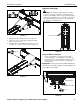
SP-WALLKIT-02 Installation Instructions Projector Installation to Mount WARNING: IMPROPER INSTALLATION CAN LEAD TO PROJECTOR FALLING RESULTING IN SERIOUS PERSONAL INJURY OR DAMAGE TO EQUIPMENT. Make certain mounting slots in mount base slide under thumb screws and that screws are seated in the back of slots. WARNING: IMPROPER INSTALLATION CAN LEAD TO PROJECTOR FALLING RESULTING IN SERIOUS PERSONAL INJURY OR DAMAGE TO EQUIPMENT. DO NOT substitute hardware.
Installation Instructions SP-WALLKIT-02 Pitch Adjustment Cable Management (Optional) NOTE: Pitch can be adjusted using the projector mount or the 1. Remove two screws #8-32 x 1/2" Phillips pan machine screws (F) to release mount cover. (See Figure 23) 2. Slide mount cover away from wall mount. (See Figure 23) pitch of the entire arm can be adjusted. See "Pitch Adjustment - Entire Arm Section for details. 1. Loosen Pitch adjustment locking screw using a #2 Phillips screwdriver. (See Figure 21) 2.
SP-WALLKIT-02 Installation Instructions • 4 Routing Cables from Above (Step 6) 6. Thread cables down through a surface mount cable accessory (not included), then behind and into the wall bracket. (See Figure 27) Proceed to Step 7 7. Route cables through cover mount, projector arm tunnel and into projector. (See Figure 28) cable clips x4 cables (view from front) Surface Mount Cable Accessory (not included) 6 Figure 25 5. Thread cable up wall bracket channel and into opened cable clips.
Installation Instructions 8. SP-WALLKIT-02 (Optional) Cables can be tied to inside of projector’s front cover using cable ties (not included). Route cables near front cover and wrap cable tie through slots on front cover and around cables. (See Figure 29) cable tie (not included) 10 Figure 31 8 route through slots and around cables 11. Reinstall two #8-32 x 1/2" Phillips pan machine screws (F) through holes on sides of outer cover. (See Figure 32) 11 (F) x 2 Figure 29 9.
SP-WALLKIT-02 Installation Instructions Adjustments Installation of Wall Bracket Covers NOTE: If security screws are going to be used, use the security screws (V) to install wall bracket covers. See Security Screw Installation section for details. 1. Place wall bracket top covers (C) over top of each wall bracket arm. (See Figure 33) projector arm not shown for display purposes Bracket Width Adjustment 1. Loosen two flat head cap screws on wall bracket. (See Figure 35) 2.
Installation Instructions SP-WALLKIT-02 4 6 5 pitch adjustment screw or 2 8 Figure 39 3. Figure 37 8. Loosen two 1/4-20 x 5/8" hex head cap screws (E) on underside of mounting bracket. (See Figure 38) Slide outer cover of mount (A) back against mounting bracket. (See Figure 39) 9. Reinstall two #8-32 x 1/2" Phillips pan machine screws (F) through holes on sides of outer cover. (See Figure 40) (bottom view) 9 3 7 (F) x 2 (E) x 2 Figure 38 4.
SP-WALLKIT-02 Installation Instructions Extension Adjustment 1. Loosen two bolts holding stop bracket in place on underside of short throw projector mount. (See Figure 41) 2. Adjust mount to desired extension length. (See Figure 37) 3. Tighten two bolts holding stop bracket to secure mount in desired position. (See Figure 41) (bottom view) 6 1 3 2 2 Figure 43 Figure 41 3. Loosen two 1/4-20 x 5/8" hex head cap screws (E) on underside of mounting bracket. (See Figure 44) 4.
Installation Instructions SP-WALLKIT-02 Security Screw Installation (Optional) 1. Remove eight #8-32 x 1/2" Phillips pan machine screws (F) from wall bracket covers. (See Figure 45) 3 1 (F) x 8 projector arm not shown for display purposes 4 Install eight #8-32 x 1/2" button head security screws (V) into holes in wall bracket covers. (See Figure 46) 2 (V) x 2 Figure 47 Figure 45 2. (F) x 2 5. Remove two bolts holding stop bracket in place on underside of short throw projector mount.
SP-WALLKIT-02 6. Installation Instructions Install two 1/4-20 x 1/2" button head security screws (T) through holes in stop bracket and into holes in sliding nuts. (See Figure 49) adapter plate stop bracket sliding nuts x 4 (one at a time) 8 Figure 50 6 (T) x 2 9. Figure 49 7. (Optional) Remove projector from short throw projector mount according to projector interface instructions. NOTE: It will be necessary to remove projector prior to install four security screws to projector bracket.
Installation Instructions Visit the InFocus support site at www.infocus.
SP-WALLKIT-02 Installation Instructions InFocus Corporation 13190 SW 68th Parkway, Ste 200 Portland, OR 97223 8802-002043 Rev00 2010 InFocus Corporation www.infocus.