
Technology Power Supply User's Manual

EonStor A16E-G2130-4 Installation and Hardware Reference Manual
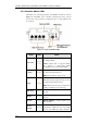
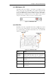
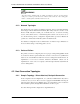
3.2.3 Controller Module LEDs
The LEDs on the rear-facing faceplate of the RAID controller are shown in
Figure 3-2. The LEDs on the controller’s faceplate that can be accessed
from the rear of the enclosure are numbered from 1 to 6. The definitions are
shown below.
Figure 3-2: Controller Module LEDs
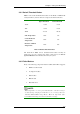
Name Color Status
Ctlr Status
Green/
Amber
Green indicates that the RAID subsystem is
operating healthily.
Amber indicates that a component failure
has occurred, or inappropriate RAID
configurations have caused system faults.
C_Dirty Amber
ON indicates that there are certain amounts
of cached data held in memory.
OFF indicates that the cache is clean.
Temp. Amber
ON indicates that the detected
CPU/board/chassis temperature has exceeded
the higher temperature threshold.
OFF indicates that the detected temperature
reading is within the preset safe range.
BBU Link Green
ON indicates the presence of a BBU backup
module.
Hst Bsy Green
Rapidly Blinking to indicate traffic on the
host bus.
Drv Bsy Green
Rapidly Blinking to indicate traffic on the
drive channels.
Restore
Default
Green
Lit Green to indicate the RAID
configuration default has been successfully
restored. The LED state will be invalidated
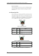
Status-indicating LEDs
3-4