
Installation Manual


ECO-X / IL-X Manual
IM100117
RD: NOV 2009
RL: 05B - BA
16
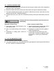
11. INSTALLATION
A. Properly size and install ventilation as per Section 8, gas supply as outlined in Section 9,
previous page, and electrical supply as per Section 10 above.
B. Ensure adequate clearance around air openings into the combustion chamber
C. Suspended infrared heaters shall be fixed in position independent of gas and electric supply
lines. Hangers and brackets shall be of non-combustible material. Heaters subject to vibra-
tion shall be provided with vibration-isolating hangers. Suspension hardware must be of
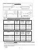
adequate capacity to support the weight of the heater - see Table 4
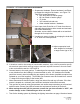
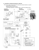
D. Mount heaters to structure by using non-combustible mounting hardware such as that illus-
trated in FIGURE 4.
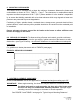
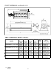
E. Mounting at an angle of up to 30° on short axis (long axis level): see Figure 5
Rotate on the short axis only - long axis must always be horizontal
The ‘center of gravity’ of the heater allows angle mounting up to 30°
Fasten suspension hardware through holes at each end and each side of the heater
body—see Figure 5 below, and Figure 6 next page
F. Observe the minimum clearances to combustibles as per the Clearance To Combustibles
section and Figure 1 and Table 1 page 7.
continued ...
FIGURE 4: TYPICAL MOUNTING HARDWARE (supplied by others)
S
S
0° to
30°
Long axis always level
7/16” (8 mm) holes for
suspension hardware
FIGURE 5: SUSPENDING HEATER - see also Figure 6 next page