Perform operations as described in “connecting cables” chapter and connect cables as follow: Cables to plug: Power lead Telephone line Ethernet cable Serial link RS232 cable If you need extra cables then cut undesired over-molded section at Install through-holes in the lead-through guides (as indicated on the figure).
ADVICE It is strongly recommended to secure the “Magic cable” to terminal’s work area in order to reduce stress on terminal and connection. Using the supplied cable tie to attach to a table leg (or similar) Using the supplied cable tie and self-adhesive support Using a counter-sunk screw (not supplied) to an appropriate surface The “Magic Cable” should be readily accessible for terminal maintenance and helpdesk diagnosis purposes.
4_5 Installing SAM (Secure access module) CAUTION Before starting, switch off the terminal by disconnecting the power supply. WARNHINWEIS Bevor Sie beginnen, das Gerät auszuschalten, indem Sie das Netz. Perform the following operations: Open down side trapdoor Insert the SAM Card into the slot marked (1) or (2). Take care to ensure that the SAM Card is inserted in the correct manner. The cut corner must be positioned as indicated on the figure.
Cut corner Adhesive CAUTION Do not use any tools when installing or removing the SAM Card. WARNHINWEIS Zum Einsetzen oder Entfernen der SAM Karte keinerlei Werkzeug benutzen. 4_6 Installing MicroSD Card (optional) CAUTION Before starting, switch off the terminal by disconnecting the power supply. WARNHINWEIS Bevor Sie beginnen, das Gerät auszuschalten, indem Sie das Netz.
4_7 Installing SIM for GPRS (optional) CAUTION Before starting, switch off the terminal by disconnecting the power supply. WARNHINWEIS Bevor Sie beginnen, das Gerät auszuschalten, indem Sie das Netz. Open down side trapdoor Cut corner Insert the SIM GPRS into the slot marked (SIM1) as indicated on the figure. Take care to ensure that the SIM is inserted in the correct manner. The cut corner must be positioned as indicated on the figure. Close down side trapdoor.
4_8 Installing SAM3 (optional) CAUTION Before starting, switch off the terminal by disconnecting the power supply. WARNHINWEIS Bevor Sie beginnen, das Gerät auszuschalten, indem Sie das Netz. Open down side trapdoor Insert the SAM Card into the slot marked (3) as indicated on the figure. Take care to ensure that the SIM is inserted in the correct manner. The cut corner must be positioned as indicated on the figure. Cut corner Close down side trapdoor.
4_9 Installing 2nd SIM for GPRS (optional) CAUTION Before starting, switch off the terminal by disconnecting the power supply. WARNHINWEIS Bevor Sie beginnen, das Gerät auszuschalten, indem Sie das Netz. Open down side trapdoor nsert the SIM GPRS into the slot marked (SIM2) as indicated on the figure. Take care to ensure that the SIM GPRS is inserted in the correct manner. The insertion position SIM corner (engraved on the terminal) must be located as shown on figure.
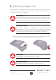
5_Installing a paper roll Your terminal is supplied with one paper roll. When the paper roll is nearing the end, a red line will appear on the paper; this indicates that the paper roll must be replaced. CAUTION Use only paper approved by the manufacturer (diameter 40 mm). Use of unsuitable paper is likely to damage the printer of your terminal (see paper characteristics at “Maintenance” chapter). WARNHINWEIS Nur vom Hersteller zugelassenes Papier benutzen (Durchmesser 40 mm).
Insert the paper roll in the compartment following the directions shown on the figure below. Pull the paper up to the top of the terminal and hold it in this position. Maintain the paper and close the lid. Press the top of the lid in the centre as shown by arrow, until it clips into position. ADVICE If you are inserting a new paper roll remove the first complete turn (this first turn of sensitive surface could be damaged during shipment).
6_Daily use 6_1 Keypad functions NAVIGATION keys Ingenico key CANCEL key (red) CLEAR key (yellow) / Feed paper (long press) VALIDATION key (green) Dot key Desk Series 900024281 R11 000 01/0116 26 Copyright© 2016 Ingenico All rights reserved
6_2 Adjusting the contrast (B&W display only) No contrast management for the Color display If you wish to increase or to decrease the contrast of the characters displayed on screen, press simultaneously on the (dot key) and key to decrease the contrast, or the (dot key) and increase it. Keep pressing the keys as long as necessary. key to 6_3 Card insertion 6_3_1 Swiping a card Insert the card manually in the driver, magstripe facing the main body of the terminal.
6_3_3 Reading Contactless (Optional) Bring the card firmly up to the active zone above (at about 1cm) the contactless logo located on paper trapdoor button. Contactless Active zone Keep the card close to the contactless logo during the transaction Your contactless terminal provides four contactless status lights located on display/ lens.
6_3_4 Headphone output (Optional) The headphone output jack is located under the card reader outlet. This option is not designed to play music, but to facilitate the use by blind people. Die Kopfhörerbuchse ist unter der Chipkartenleser entfernt. Diese Option ist nicht für die Musik zu spielen, aber nur, um die Verwendung von blinden Menschen zu erleichtern. 7_Maintenance / Wartung CAUTION Before making any operations of maintenance in the terminal, make sure that the power supply is disconnected.
direct contact with materials containing plasticizers (PVC transparent folders or envelopes) direct contact with «diazo» papers direct contact with water Rubbing or pressing the paper too strongly CAUTION In order to benefit from the complete guarantee of the product, use manufacturer approved thermal paper only. WARNHINWEIS Um in den vollen Genuss der Garantie zu kommen, darf nur vom Hersteller zugelassenes wârmeempfindliches Papier benutzt werden.
Avoid exposing the terminal to the direct rays of the sun. Do not put anything into the slot of the smart card reader 7_3 Transport and storage Use the original packaging for any unit or stored. Disconnect all cables from the terminal during the transport.
7_5 Environment (WEEE, Batteries and Packaging) This product is labeled in accordance with European Directives 2002/96/EC concerning Waste Electrical and Electronic Equipment (WEEE) and 2006/66/EC concerning Batteries and Accumulators. Those provisions are requiring producers and manufacturers to become liable for take-back, treatment and recycling upon end of life of equipment and batteries.
This marking indicates that the product operates with an alternating current (AC) source (mains). It is completed by afferent values (voltage, frequency and max current). This marking indicates that your terminal is suitable for direct current (DC) only. It is completed by afferent values (voltage, and max current). This marking indicates power supply meets the energy efficiency level V requirements. Marking for Class II product. Such product does not require a safety connection to electrical earth.
8_1 FCC/IC Compliance FCC ID: XKB-D5000M00 / XKB-D5000M01 IC: 2586D-D5000M00 / 2586D-D5000M01 This equipment has been tested and found to comply with the limits for a Class B digital device, pursuant to part 15 of the FCC Rules. These limits are designed to provide reasonable protection against harmful interference in a residential installation.
Le présent appareil est conforme aux CNR d’Industrie Canada applicables aux appareils radio exempts de licence. L’exploitation est autorisée aux deux conditions suivantes : (1) l’appareil ne doit pas produire de brouillage, et (2) l’utilisateur de l’appareil doit accepter tout brouillage radioélectrique subi, même si le brouillage est susceptible d’en compromettre le fonctionnement.
No changes shall be made to the equipment without the permission of Ingenico as this may void the user’s authority to operate the equipment. Tout changement apporté à ce terminal non expressément approuvé par Ingenico est susceptible d’annuler le droit de l’utilisateur à se servir de cet équipement. Part 68 of FCC Rules US: IEOMM02TD5000M00 / IEOMM02TD5000M01 This equipment complies with Part 68 of the FCC rules and the requirements adopted by the ACTA.
If your home has specially wired alarm equipment connected to the telephone line, ensure the installation of this equipment does not disable your alarm equipment. If you have questions about what will disable alarm equipment, consult your telephone company or a qualified installer. U.S.A service center: Ingenico North America 3025 Windward Plaza, suite 600 Alpharetta, GA 30005 USA Tel: +1(678) 456 1200 Fax: +1 (678) 456 1201 Email: info.us@ingenico.
“This Document is Copyright © 2016 by INGENICO Group. INGENICO retains full copyright ownership, rights and protection in all material contained in this document. The recipient can receive this document on the condition that he will keep the document confidential and will not use its contents in any form or by any means, except as agreed beforehand, without the prior written permission of INGENICO.