
User's Manual


1. Terminal description:
1.1 Introduction:
The Elite 790 is a fully self-contained RF EFTPOS
terminal with an integrated printer and the
functionality to process all smart card, debit and
credit purchases. The terminal communicates with
the bank using the RF data network or via the
telephone network by using a Fast or Slow Charging
Base. This RF network is similar to that used for
mobile phones except that it supports data as well.
The terminal features a secure, multi-application
operating system, which allows a number of
different applications to run on the terminal
independently, without jeopardizing software
security.
1.2 The Terminal:
The Elite 790 terminal has the following features:
1.2.1 Display:
A 4 line x 16 character LCD graphic display, with
back lighting.
1.2.2 Navigation Button:
Allows scrolling through options and selection of the
desired option.
1.2.3 Keypad:
• 18 keys, with back lighting, with the following
special function keys:
• F1, F2, and F3 keys: Programmable keys which
permit access to terminal level functions and the
system menu.
• Paper Feed key: Performs a 20mm paper feed.
• ENTER key: is used to confirm the data entered
or displayed.
• CAN key: is used to cancel the current function
and return the terminal to the idle state.
• CORR key: is used to correct any invalid data
entry.
• ADMIN key: is used to access the terminal
administration function menu.
1.2.4 Magnetic Stripe Card Reader:
This is a bi-directional reader capable of reading
simultaneously Tracks 1&2, and it is located just above
the display. The Magnetic Stripe on the card should
face down and to the rear of the Elite 790 terminal. The
card should be swiped at uniform speed and pressure,
ensuring that the card remains in contact with the
bottom of the track throughout the entire swipe action.
1.2.5 RF and Telephone Modem:
The modem allows data exchange over an RF network.
1.2.6 Printer:
The built-in printer is a high-speed thermal printer (6
lines per second) and is graphics compatible.
1.2.7
Smart Card Reader:
Complies with standard ISO 7816, Sync & Async and
EMV Level 1. The Elite 790 is equipped with a Smart
Card Reader slot located at the front of the terminal.
1.2.8 RS232:
The RS232 port allows download of customer
applications and connection of external peripherals.
1.2.9 Hands Free Connector:
Jack for the hands free kit (earpiece and microphone).
1.3 The Slow/Fast Charging Base and Slow
Charging Vehicle Base:
Three bases are available: slow charging base, fast
charging base and slow charging vehicle base. The
slow charging vehicle base is used only for charging
the terminal’s battery. The slow & fast charging bases
have an interface to the telephone network, support
applications downloading and the battery recharging.
1.4 Elite 790 Terminal Package Contents:
1. The Elite 790 terminal with a battery pack.
2. Thermal printer paper, one roll.
3.
Installation Guide
1.5 Elite 790 Charging Base Package Contents:
1. The Elite 790 base (slow, fast or vehicle charging).
2. Installation Guide.
3. Cable from Vehicle Base to car battery
4. 4 mounting screws for Vehicle Base
5. Power supply (not supplied with the vehicle base).
6. Phone cable (not supplied with the vehicle base).
2. Installation procedure:
Important Note: Before using the Elite 790
terminal for the first time, the battery pack must
be fully charged. The battery must be charged at
least 2 hours if the fast charge base is used, or 16
hours if the slow or vehicle slow charge base is
used.
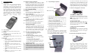
2.1 Paper loading (If required):
1.
Open the paper compartment cover.
2. Move the paper load lever forward to disengage the
friction roller.
3. Remove the empty paper roll by pressing the roll
release lever on the right hand side.
4. Position the paper roll with the end of the roll
protruding from UNDERNEATH the roll.
5. Feed the paper under the printer’s roller until it
protrudes from the top of the printer.
6. Fit the paper roll to the spindle and move the paper
load lever back to engage the friction roller.
7. Close the cover and test the operation of the printer
by Pressing Paper Feed key.
2.2 SIM Installation:
Access to the optional SIM slots is through the battery
door located on the underside of the Elite 790 terminal.
Access to the GSM SIM is through a “trap door” which
opens only when the battery pack is removed.
To unlock the SIM holder, slide the metal clasp
towards the hinge. Swing the SIM holder up. Insert
the SIM card in between the metal clasp and the
plastic holder, with the metal plate facing down.
Swing the SIM holder down. To lock the SIM card
in place, slide the metal clasp away from the hinge.
2.3 Slow/Fast Charging Base Connection
TELEPHONE CONNECTION
The telephone cable used with the Elite 790 must be
plugged into the base port marked with the symbol
. The other end of the cable must be connected
to a wall telephone jack.
POWER CONNECTION
The radial connector on the power pack must be
plugged into the port marked with the symbol
.
The two prong electrical plug must be connected in
the wall electrical socket.
CONNECTION TO AN EXTERNAL
PERIPHERALS
P
eripheral devices can be connected to the RS232
port of the Elite 790. The Elite 790 base and
terminal must be powered off before connecting the
cable to the RS232 port.
2.4
Vehicle Slow Charging Base Connection
This must be connected directly to the vehicle
12VDC battery through an appropriate cable.
Alternatively an optional cigarette lighter adapter is
available. Make sure to use the cigarette lighter
adapter provided by INGENICO. Other brands may
prevent proper operation or damage the Elite 790
terminal and base.
GSM SIM
SIM No 1
Paper Load Lever
Roll Release Lever