GSM/GPRS Embedded Data/Fax/Voice Wireless Modem MTMMC-G-F1 MTMMC-G-F2 Developer’s Guide
ModemModule Developer’s Guide MTMMC-G-F1 and MTMMC-G-F2 PN S000295A, Version A 07/15/03 Copyright This publication may not be reproduced, in whole or in part, without prior expressed written permission from Multi-Tech Systems, Inc. All rights reserved. Copyright © 2003, by Multi-Tech Systems, Inc. Multi-Tech Systems, Inc. makes no representations or warranties with respect to the contents hereof and specifically disclaims any implied warranties of merchantability or fitness for any particular purpose.
Table of Contents CHAPTER 1 – PRODUCT DESCRIPTION AND SPECIFICATIONS ................................................................5 INTRODUCTION ...........................................................................................................................................................5 Scope of the Developer Guide ................................................................................................................................5 GENERAL CHARACTERISTICS ........................
GENERAL GUIDELINES FOR THE USE OF THE MODEMMODULE .................................................................................37 Hardware and RF.................................................................................................................................................37 The Antenna..........................................................................................................................................................37 Firmware Upgrade...............................
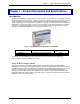
Chapter 1 – Product Description & Specification Chapter 1 – Product Description and Specifications Introduction ModemModule GSM/GPRS integrated wireless modems provide a quick and easy way to insert GSM and GPRS functionality into systems and terminals. Available in dual-band configurations, this fully type approved integrated modem constitutes a self-contained, fully integrated implementation of the GSM/GPRS standard. Thanks to standard interfaces, it can be integrated into any system.
Chapter 1 – Product Description & Specification General Characteristics General · · · · · · · · · · · · · · · · · GPRS Class 10 Dual Band GSM/GPRS modem E-GSM 900/1800 or GSM 850/1900 2W at 850MHz 1W at 1800/1900 MHz GSM Class 1 and Class 2 Group 3 FAX Small size and low power consumption Voice and Short Message Services (SMS) Fax and data transmission without extra hardware Serial interface supports DTE speeds up to 115.2K MMCX connector and SIM socket 14.
Chapter 1 – Product Description & Specification GSM Circuit Data Features · · · · · Data circuit asynchronous, transparent and non transparent up to 14,400 bits/s Automatic fax group 3 (Class 1 & 2) Alternate speech and fax MNP2, V.
Chapter 1 – Product Description & Specification Feature Descriptions Integration Reduces Space, Power and Cost. The ModemModule GSM/GPRS integrates the controller, RF transceiver, and antenna interface in one compact unit. This integration requires low power, occupies very little space, and provides an overall reduction in costs. Reduces Development Time.
Chapter 1 – Product Description & Specification Applications With circuit switched data rates up to 14.4K bps, the MultiModem GSM/GPRS is targeted at applications that periodically need to send or receive data over a wireless network. It is an ideal device for: Appliances Remote Diagnostics ATM Terminals Remote Metering Automotive Security Systems Data Collection Vending/Gaming Machines Gas Pumps Other devices requiring wireless connectivity.
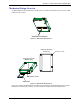
Chapter 1 – Product Description & Specification Mechanical Design Overview The ModemModule is encased as shown in the figure below. It includes a RF module, a 50-pin connector, a SIM holder and a RF connector. Interface Connector Figure 1-2: Mechanical Description A Holes for Mounting Screws (4) Hole dia. = 0.087” Antenna Connector (MMCX type) SIM ejection button SIM Reader Figure 1-3: Mechanical Description B Four screw holes allow the ModemModule to be fixed on the mother PCB.
Chapter 2 – Mechanical Specifications Chapter 2 – Mechanical Specifications Mechanical Dimensions Figure 2-1: ModemModule Dimensions Wireless ModemModule MTMMC-G-F1 and MTMMC-G-F2 Developer’s Guide 11
Chapter 2 – Mechanical Specifications Climatic and Mechanical Environment Testing Compliance Table 2-1 : Climatic and Mechanical Environment Testing Compliance G900/G1800 Environmental Type of Test Standards Storage Class 1.2 Cold IEC 68-2.1 Ab test -25 C; 72 hours Dry Heat IEC 68-2.2 Bb test +70 C; 72 hours Change of Temperature IEC 68-2.14; Damp Heat Cyclic IEC 68-2.30; Db test +30 C; 2 cycles 90% - 100% RH variant 1 Damp Heat IEC 68-2.56 +30 C; 4 days Sinusoidal Vibration IEC 68-2.
Chapter 3 – Electrical Characteristics Chapter 3 – Electrical Characteristics Introduction This chapter describes the ModemModule’s electrical interfaces.
Chapter 3 – Electrical Characteristics 50-Pin Connector Interfaces 50-Pin Connector Description Table 3-1.
Chapter 3 – Electrical Characteristics Table 3-1.
Chapter 3 – Electrical Characteristics Table 3-2. Operating Conditions Parameter I/O Type Min Max Vinput low CMOS -0.5V 0.8V Vinput high CMOS 2.1V 3.0V Voutput low 1X 0.2V IOL = -1mA 2X 0.2V IOL = -2mA 3X 0.2V IOL = -3mA Voutput high Condition 1X 2.6V IOH = 1mA 2X 2.6V IOH = 2mA 3X 2.
Chapter 3 – Electrical Characteristics 50 49 2 1 Figure 3-2: Pin Numbering – Bottom View Power Supply The main power supply is provided through a double connection. These connections are respectively pins 3 and 4 for the +5V and the pins 1 and 2 for the ground (GND). The pins 6, 21, and 24 are also ground connection in order to produce a proper ground plane. A 5V +/-5% - 1A power is strictly required to supply the modem. Otherwise, serious dysfunctions may appear.
Chapter 3 – Electrical Characteristics Table 3-5: Power Consumption in GSM-only 1800 & 1900 MHz modes @25 degrees C Conditions INOM IMAX +5V During TX bursts @1W 635 mA 800 mA +5V Average @1W 260 mA 280 mA +5V Average @ 0.25W 150 mA 170 mA +5V Average idle mode 20 mA 22 mA Table 3-6: Power Consumption in EGSM/GPRS 900 MHz and GSM/GRPS 850 MHz Mode Class 10 Conditions INOM IMAX +5V During TX bursts @PcI5 1.7 A peak 2.
Chapter 3 – Electrical Characteristics Serial Link A serial link interface is available complying with V24 protocol signaling but not with V28 (electrical interface) due to a 2.8 Volts interface. TX, RTS and DTR can be either 5V or 3V. The signals are Tx data (CT103/TX), Rx data (CT104/RX), Request To Send (CT105/RTS), Clear To Send (CT106/CTS), Data Terminal Ready (CT108-2/DTR) and Data Set Ready (CT107/DSR). The set of RS232 signals can be required for GSM DATA services application.
Chapter 3 – Electrical Characteristics Level Shifter Modem 28 Vcc C1+ 27 25 C11 C2+ 3 Vcc RI 2 26 4 C2- 24 T1IN T1OUT DCD 23 T2IN T2OUT RX 22 T3IN T3OUT CTS 19 DSR 17 16 DTR 21 TX 20 RTS 18 Vcc 13 Terminal T4IN T4OUT T5IN T5OUT GND 5 S_RI 6 S_DCD 7 S_RX 10 S_CTS 12 S_DSR R1OUTB R1IN 8 S_DTR S_TX R2OUT R2IN 9 11 R3IN R3OUT R4OUT ON ERROR 15 14 OFF Vcc GND S_RTS Vcc MAX 3238 *This application note is valid for Vcc> 3.
Chapter 3 – Electrical Characteristics Power OFF Procedure In order to power OFF the ModemModule, switch it OFF both via software (AT+CPOF; see AT Command Manual for more details) and via hardware line. See the diagrams below.
Chapter 3 – Electrical Characteristics BOOT This input is used to switch the ModemModule into download mode (backup procedure). The internal boot procedure is started when this pin is low during the power ON of the module. In normal mode, this pin has to be left open. If used, this input has to be driven by an open collector or an open drain. See below an example of application diagram. See also the “Firmware Upgrade” section of Chapter 5: Application Considerations.
Chapter 3 – Electrical Characteristics Table 3-11: Reset Signal Pin Description Signal Pin Number I/O ~RST 19 I/O I/O Type* Description Module reset * See “Table 3-2: Operating Conditions” in section on the 50-pin Connector Description. Table 3-12: Reset Signal Electrical Characteristics Parameter Min Input Impedance ( R ) 4.7 Max Unit kilo-ohms Input Impedance ( C ) 10 nanofarads Table 3-13: Reset Signal Operating Conditions Parameter Min Max *VT- 1.1 V 1.2 V *VT+ 1.7 V 1.
Chapter 3 – Electrical Characteristics General Purpose Input/Output The ModemModule provides two General Purpose I/O connections. They can be used to control any external device. Table 3-16 : General Purpose I/O Pin Description Signal Pin Number I/O I/O Type* Description Default Value GPIO0 26 I/O CMOS / 2X General Purpose I/O 0 GPIO4 7 I/O CMOS / 2X General Purpose I/O 0 * See “Table 3-2: Operating Conditions” in section on the 50-pin Connector Description.
Chapter 3 – Electrical Characteristics Audio Interface Two different microphone inputs and two different speaker outputs are supported. The connection can be either differential or single-ended but using a differential connection in order to reject common mode noise and TDMA noise is recommended. Microphone 2 Inputs The MIC2 inputs are differential ones. They already include the convenient biasing for an electret microphone (0,5 mA and 2 Volts).
Chapter 3 – Electrical Characteristics Microphone 1 Inputs The MIC1 inputs are differential and do not include internal bias. To use these inputs with an electret microphone, bias has to be generated outside the ModemModule according to the characteristic of this electret microphone. These inputs are the standard ones used for an external headset or a hands-free kit.
Chapter 3 – Electrical Characteristics Speaker 2 Outputs Speaker outputs SPK2 are push-pull amplifiers and can be loaded down to 50 Ohms and up to 1nF. These outputs are differential and the output power can be adjusted by step of 2dB. The output can be directly connected to a speaker. When using a single-ended connection, be sure to have a very good ground plane, a very good filtering as well as shielding in order to avoid any disturbance on the audio path.
Chapter 3 – Electrical Characteristics Speaker 1 Outputs Speaker outputs SPK1 are push-pull amplifiers and can be loaded down to 50 Ohms and up to 1nF. These outputs are differential and the output power can be adjusted by step of 2dB. The output can be directly connected to a speaker. When using a single-ended connection, be sure to have a very good ground plane, a very good filtering as well as a shielding in order to avoid any disturbance on the audio path.
Chapter 3 – Electrical Characteristics SIM interface The external SIM interface is available through the 50-pin connector in order to use a stand-alone SIM cardholder. 5V SIMs can be driven using an external level shifter. SIM line must not exceed 15 cm. See also the “Hardware and RF” section of Chapter 5: Application Considerations. Five signals are available: SIMVCC: SIM power supply. SIMRST: reset. SIMCLK: clock. SIMDATA: I/O port. SIMPRES1 SIM card detect.
Chapter 3 – Electrical Characteristics Table 3-24: SIM Interface Electrical Characteristics Parameter Conditions Min Typ SIMDATA VIH IIH = +/- 20mA 0.7xSIMVCC SIMDATA VIL IIL = 1 mA SIMRST, SIMDATA SIMCLK VOH Source current = 20mA SIMRST, SIMDATA SIMCLK VOL Sink current = -200mA SIMVCC Output Voltage ISIMVCC <= 6mA SIMCLK Rise/Fall Time Max Unit V 0.3xSIMVCC SIMVCC – 0.1V V V 0.1 2.70 2.80 2.
Chapter 3 – Electrical Characteristics GND SIMVCC 1 VCC SIMRST 2 RST SIMCLK 3 CLK CC4 GND VPP IK SIMDATA 7 I/O SIMPRES1 8 CC8 Figure 3-12: SIM Socket SPI Bus The SPI bus includes a CLK signal, an I/O signal and an EN signal complying with SPI bus standard. The maximum speed transfer is 3.25Mb/s.
Chapter 4 – Interfaces Chapter 4 – Interfaces This chapter describes the ModemModule interfaces. · Flashing LED · SIM Interface · RF Interface · DTE/DCE Interface Rates Flashing LED The flashing LED signal is used to indicate the working mode of the ModemModule.
Chapter 4 – Interfaces RF Interface The impedance is 50 Ohms nominal. RF Connector The RF connector is MMCX standard type. An antenna can be directly connected through the matting connector or using a small adapter. RF Performances RF performances are compliant with the ETSI recommendation 05.05 and 11.10.
Chapter 5 – Test Board Chapter 5 – Test Board Serial Test/Demo Board Components Wireless ModemModule MTMMC-G-F1 and MTMMC-G-F2 Developer’s Guide 34
Chapter 5 – Test Board Serial Test/Demo Board Block Diagram Block Diagram for the ModemModule GSM/GPRS Wireless ModemModule MTMMC-G-F1 and MTMMC-G-F2 Developer’s Guide 35
Chapter 5 – Test Board SIM Schematic (5V) SIM interface from Modem Module. R20, R21, R22 and R23 are used to shunt LTC1555. SIMDA TA R20 SIMRST R21 0 R12 100K R22 0 R14 100K SIMCLK 2 C_GPO0 3 47K 47K 1 10K GND GND GND U4 4.7K 4 0 5 UMC5NT1 VCC = 2.8V GND SIMV CC V CC GND R13 100K 1 2 3 4 5 6 7 8 U6 CIN RIN DA TA DDRV DV CC SS M1 M0 CLK RST I/O V CC V IN C1+ C1GND 16 15 14 13 12 11 10 9 C28 .1uF GND 1K C43 2.
Chapter 6 – Application Considerations Chapter 6 – Application Considerations General Guidelines for the Use of the ModemModule Hardware and RF · · · · · · Ground plane: MultiTech recommends having a common ground plane for analog, digital and RF grounds. Length of the SIM interface lines (15 cm maximum) Bias of the Microphone inputs must be properly adjusted when using audio connectors (mic + speaker) 1.
Chapter 6 – Application Considerations Getting Started Minimum Hardware Interface Required To Get Started At a minimum, it is necessary to connect the following signals too properly operate the ModemModule: Table 5-1: Minimum Signals to Operate the ModemModule Pin Number Name Description 1 GND Ground 2 GND Ground 3 +5V Power Supply 4 +5V Power Supply 6 GND Ground 13 CT106/CTS Clear to Send 15 ON/OFF Power On/Off * 21 GND Ground 24 GND Ground 25 CT103/TX Transmit 28 CT104
Chapter 6 – Application Considerations Reference Documents Table 5-2: GSM ETSI Recommendations for Phase I and Phase II Specification Reference Title GSM ph2 Radio ETSI GSM 05.05 and GT 01 v4.2.1 DCS ph2 Radio ETSI GSM05.05 and GT01 v4.2.1 GSM ph2 Link-Management ETSI GSM 03.06, 04.08, 05.05, 05.08, 05.10, 07.01 an GT 01 v4.2.1 GSM ph2 Link-Management ETSI GSM 03.06, 04.08, 05.05, 05.08, 05.10, 07.01 an GT 01 v4.2.1 GSM ph2 Layer 2 ETSI GSM 04.06 and GT 01 v4.2.1 GSM ph2 Layer 3 ETSI GSM 04.
Chapter 6 – Application Considerations Additional Information European Telecommunications Standards Institute (ETSI) - Contact the ETSI at: 650, route des Lucioles 06921 Sophia-Antipolis Cedex France Tel: +33 (0)4 92 94 42 00 Fax: +33 (0)4 93 65 47 16 Global Engineering Documents manages a collection of more than one million documents from over 460 organizations worldwide: http://global.ihs.
Appendix A – Safety Precautions & Regulatory Standards Compliance Appendix A – Safety Precautions & Regulatory Standards Compliance Safety Precautions IMPORTANT! FOR THE EFFICIENT AND SAFE OPERATION OF YOUR GSM INTEGRATED MODEM READ THIS INFORMATION BEFORE USE. RF Safety General Your ModemModule is based on the GSM standard for cellular technology. The GSM standard is spread all over the world. It covers Europe, Asia and some parts of America and Africa. This is the most used telecommunication standard.
Appendix A – Safety Precautions & Regulatory Standards Compliance General Safety Driving Check the laws and the regulations regarding the use of cellular devices in the area where you have to drive as you always have to comply with them. When using your modem while driving, please: give full attention to driving, pull off the road and park before making or answering a call if driving conditions so require.
Appendix A – Safety Precautions & Regulatory Standards Compliance RF Exposures Pursuant to 47 CFR § 24.52 of the FCC Rules and Regulations, personal communications services (PCS) equipment is subject to the radio frequency radiation exposure requirements specified in § 1.1307(b), § 2.1091 and § 2.1093 as appropriate. The MultiTech ModemModule is a GSM (PCS 1900) terminal which operates in the US licensed PCS frequency spectrum.
Appendix A – Safety Precautions & Regulatory Standards Compliance Regulatory Standards Compliance GSM compliance Reference regulations: TBR 19, TBR 20, TBR 31, TBR 32. Table B-1: ModemModule Acceptance Test Tests Applied Standard Acceptance Criteria Performance Test ETSI recommendation for GSM/DCS communication Full conformity to the recommendation regarding the main RF parameters. Cooking Test Stress Test IEC 100-4-2. The test continues even after the Cooking Test milestone has been reached.
Appendix A – Safety Precautions & Regulatory Standards Compliance FTA Compliance The ModemModule has received a Full-Type Approval (according to normal MS requirements) in the configuration using the internal SIM interface.
Appendix B – Sourcing Guide for Connectors/Peripherals Appendix B – Sourcing Guide for Connectors and Peripheral Devices Where to Find SMD Connectors The ModemModule matting interface connector is made by SAMTEC France (http://www.samtec.com/). Many SAMTEC products are available via SAMTEC dealers throughout the world. Connector data sheets are presented later in this appendix.
Appendix B – Sourcing Guide for Connectors/Peripherals GSM Antenna The integrated modem antenna connector is a MMCX connector. The MMCX connector incorporates a 'Snap On' latching action in order to make the connection easier with an excellent RF performance. An additional advantage is its small physical size which is 50% of the standard MCX connector. This type of connector is suitable for the standard ranges of flexible and semi-rigid cables.
Appendix C – AT Command List Appendix C – AT Command List For comprehensive information about AT Commands, please read the AT Command Manual.
Appendix C – AT Command List Table C-1b : AT Command List (cont’d) Call Control Commands D Dial command H Hang-up Command A Answer a Call +CEER Extended Error Report +VTD, +VTS DTMF Signals ATDL Redial Last Telephone Number AT%Dn Automatic Dialing (or SMS send) with DTR ATSO Automatic Answer +CICB Incoming Call Bearer +VGR, +VGT Gain Control +CMUT Microphone Mute Control +SPEAKER Speaker and Microphone Selection +ECHO Echo Cancellation +SIDET Side Tone Modification +VIP Initiali
Appendix C – AT Command List Table C-1c: AT Command List (cont’d) Short Message Commands +CSMS +CNMA +CPMS +CMGF +CSAS +CRES +CSDH +CNMI +CMGR +CMGL +CMGS +CMGW +CMSS +CSMP +CMGD +CSCA +CSCB +WCBM +WMSC +WMGO Select Message Service New Message Acknowledgement Preferred Message Storage Preferred Message Format Save Settings Restore Settings Show Text Mode parameters New Message Indication Read Message List Message Send Message Write Message to Memory Send Message from Storage Set Text Mode Parameters Delete
Appendix C – AT Command List Table C-1d: AT Command List (cont’d) Fax Commands +FTM +FRM +FTH +FRH +FTS +FRS Transmit Speed Receive Speed HDLC Transmit Speed HDLC Receive Speed Stop Transmission and Wait Receive Silence Fax Class 2 Commands +FDT +FDR +FET +FPTS +FK +FBOR +FBUF +FCQ +FCR +FDIS +FDCC +FLID +FPHCTO Transmit Data Receive Data Transmit Page Punctuation Page Transfer Status Parameters Terminate Session Page Transfer Bit Order Buffer Size Report Copy Quality Checking Capability to Receive Curre
Appendix C – AT Command List Table C-1e: AT Command List (cont’d) Specific AT Commands +CCED Cell Environment Description +CCED Automatic RxLev Indication +WIND General Indications +ADC Analog Digital Converters Measurements +CMER Mobile Equipment Event Reporting +WLPR Read Language Preference +WLPW Write Language Preference +WIOR Read GPIO Value +WIOW Write GPIO Value +WAC Abort Command +WTONE Play Tone +WDTMF Play DTMF Tone +WDWL MultiTech Downloading +WVR MultiTech Voice Rate
Appendix D – Acronyms and Abbreviations Appendix D – Acronyms and Abbreviations ADC : Analog Digital Converter ASIC : Application Specific Integrated Circuit BCCH : Broadcast Control Channel CE : Communauté Européenne CLK : Clock CTS : Clear To send dB : decibel DCD : Data Carrier Detect DCE : Data Circuit Terminating Equipment DSR : Data Set Ready DTE : Data Terminal Equipment DTR : Data Terminated Ready EFR : Enhanced Full Rate E-GSM : Extended- GSM EMC : Electromagnetic Conformity EN : Enable ETSI : Eur
Appendix D – Acronyms and Abbreviations Index 1 1X ....................................................14, 15, 16, 19, 31 2 2X ........................................14, 15, 16, 19, 23, 24, 29 3 3X ......................................................................15, 16 A advice of charge.........................................................8 Advice of Charge.......................................................7 Advice Of Charge....................................................50 analog .......
Index N nominal value ..........................................................17 O OFF............................................14, 20, 21, 23, 38, 42 ON/~OFF...........................................................14, 20 operating conditions ................................................43 P PCB ...................................................................10, 53 PCS....................................................................33, 43 phone book ...........................................
Index LIST OF FIGURES Figure 1-1: MultiTech’s Wireless ModemModule GSM/GPRS Figure 1-2: Mechanical Description A Figure 1-3: Mechanical Description B Figure 2-1: ModemModule Dimensions Figure 3-1: 50-Pin Connector Figure 3-2: Pin Numbering – Bottom View Figure 3-3: Level Shifter Application Diagram for Serial Link Figure 3-4: Power-Off Procedure 1 Figure 3-5: Power-Off Procedure 2 Figure 3-6: Boot Procedure Figure 3-7: Reset Procedure Figure 3-8: Microphone 2 Input Figure 3-9: Microphone 1 Input Figure 3-1
Index LIST OF TABLES Table 2-1 : Climatic and Mechanical Environment Testing Compliance Table 3-1a. 50-pin Connector Description Table 3-1b. 50-Pin Connector Description Table 3-2.