
User's Manual
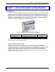
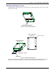
Table Of Contents
- Introduction
- General Characteristics
- Feature Details
- Feature Descriptions
- Applications
- Mechanical Design Overview
- Mechanical Dimensions
- Climatic and Mechanical Environment Testing Compliance
- Introduction
- 50-Pin Connector Interfaces
- Flashing LED
- SIM Interface
- RF Interface
- DTE/DCE Interface Rates
- Serial Test/Demo Board Components
- Serial Test/Demo Board Block Diagram
- General Guidelines for the Use of the ModemModule
- Reference Documents
- Related Manuals
- Additional Information
- Safety Precautions
- Regulatory Standards Compliance
- Where to Find SMD Connectors
- GSM Antenna
- SIM Card Holder
- LIST OF TABLES

Chapter 1 – Product Description & Specification
Wireless ModemModule MTMMC-G-F1 and MTMMC-G-F2 Developer’s Guide 10
Mechanical Design Overview
The ModemModule is encased as shown in the figure below. It includes a RF module, a 50-pin connector, a SIM
holder and a RF connector.
Interface Connector
Figure 1-2: Mechanical Description A
Holes for Mounting
Screws (4)
Hole dia. = 0.087”
SIM Reader
Antenna Connector
(MMCX type)
SIM ejection button
Figure 1-3: Mechanical Description B
Four screw holes allow the ModemModule to be fixed on the mother PCB. The ModemModule can be mounted
indifferently on both sides (top or bottom). For further details see Chapter 2: Mechanical Specifications.